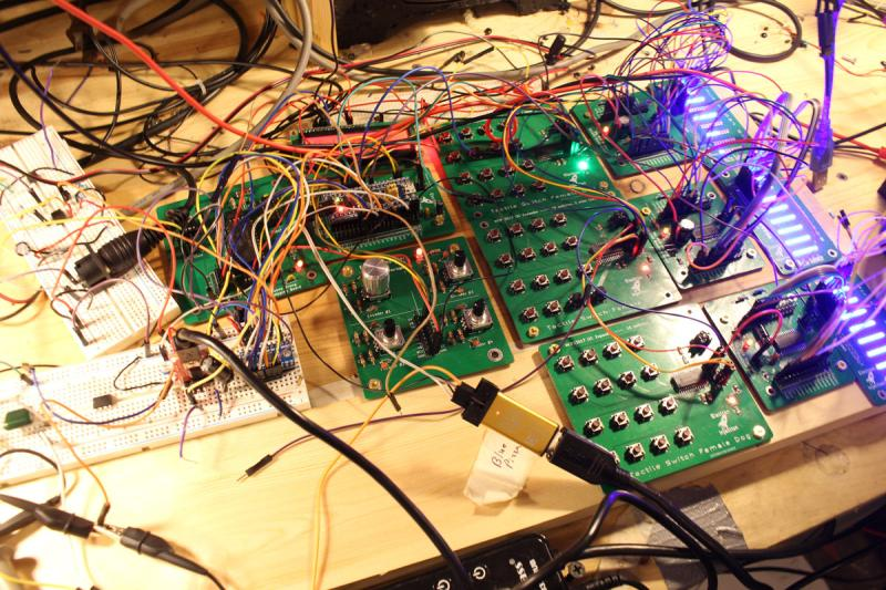
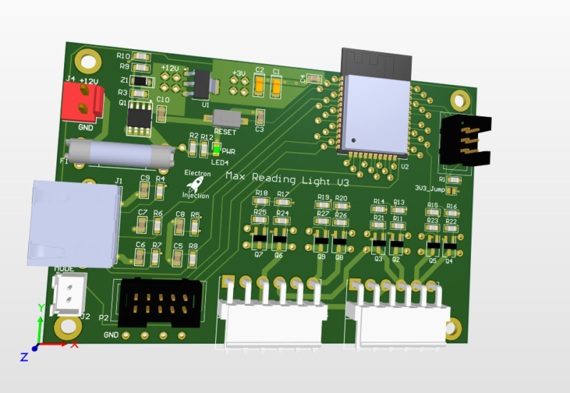
Dungeon Controller – STM32 HAL FreeRTOS
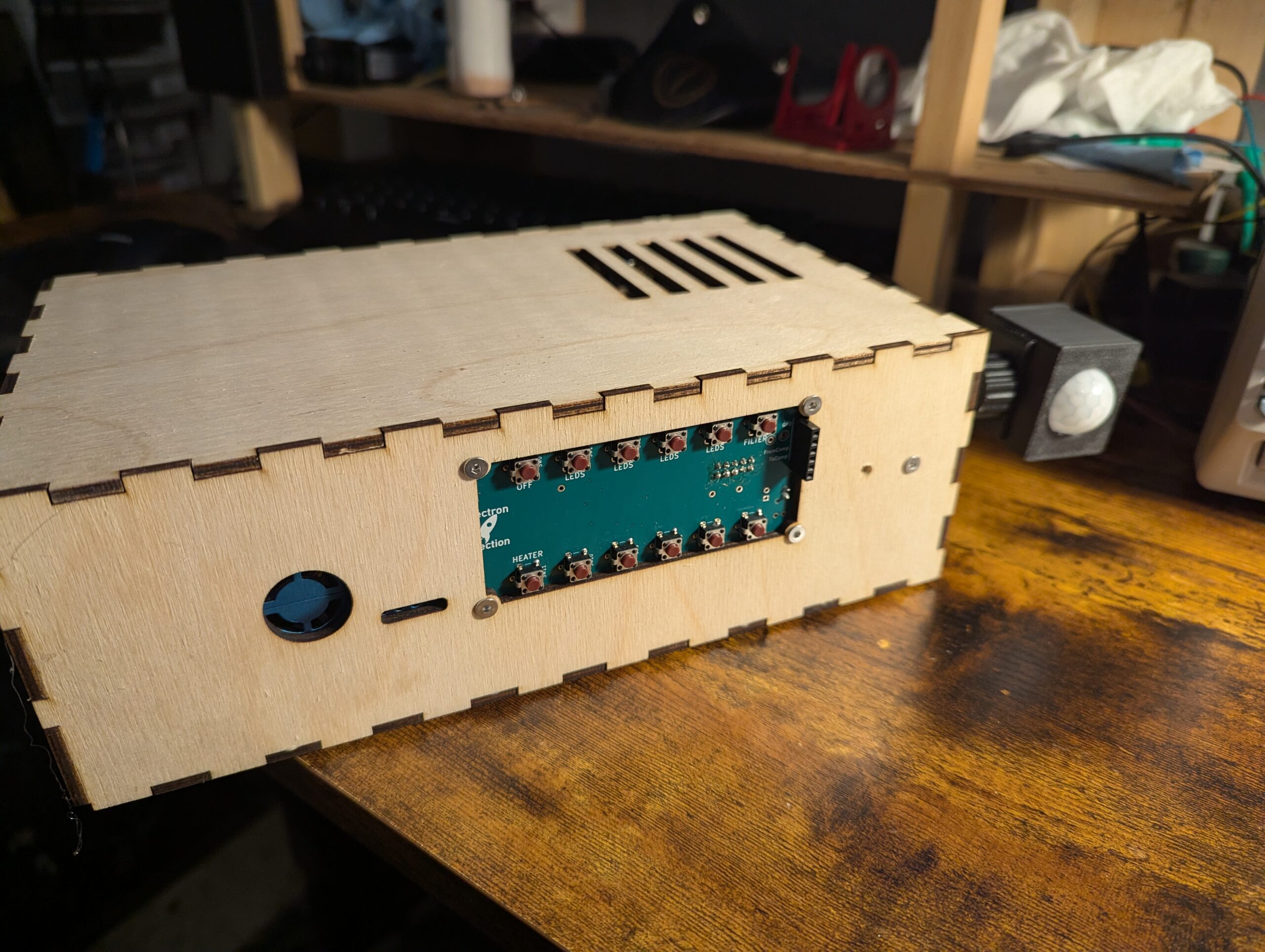
Automation system for my “dungeon”/workshop/lab for automatic handling of lighting, temperature, and air quality.
Automation system for my “dungeon”/workshop/lab for automatic handling of lighting, temperature, and air quality.
Believe it or not this is a fully functional music synthesizer with fully every possible parameter tweakable and can save presets. The synth sound horrible, but that was by design. The YM3812 chip is from an old Soundblaster card from back in the Reagan days. This thing sounds like bad dog stuff. It’s so bad … Read more

I became intrigued with the 200W+ audio amplifiers on Amazon for $80 or so on Amazon. I did a little digging and found that some were based on a TI TPA3255 chip. I picked up a few MPN: TPA3255DDV and went to town. I basically lifted this schematic directly from the datasheet so it wasn’t … Read more

My friend wanted to control the level of his home stereo system built into his house. No problem. Sorta. I bought an off the shelf Bluetooth audio receiver so phones could send audio to this thing. Ran it through my PCB and split the audio out to a couple of those Class D amplifiers based … Read more
Requirements: This was a basic project. The ESP32 is overkill for this, but I had it on hand. For linear faders that are normally used on a mixing console create voltage dividers that are read by the ADC on the ESP32. The light is dimmed with standard PWM and MOSFETs. Fun artifact. My son wanted … Read more
The world needed another USB 3.1 hub. Nevermind that they can be purchased for the cost of a sugar-laden cup of coffee. I needed this module block for the future and I always like to design these in chunks when I can.
AutoHotKeys can work with Python and Windows to become a powerhouse tool for automation.
I had hell with the drivers for the Atmel ICE to talk to the ATmega4808 so I figured I’d keep my settings here. PlatformIO platformio.ini [env:ATmega4808] platform = atmelmegaavr board = ATmega4808 framework = arduino upload_speed = 115200 upload_protocol = atmelice_updi Device Manager Looks LIke This Zadig Looks Like This
It takes about 20 seconds to put a potentiometer model in LtSpice. I have no idea why it wasn’t included. Regardless…. — Download the “Pot” folder at https://github.com/brandondrury/LTspice-Libraries — Find your C:\Users\YOUR_USERNAME\Documents\LTspiceXVII\lib\ folder— Place pot.asy in your “sym” folder. C:\Users\YOUR_USERNAME\Documents\LTspiceXVII\lib\sym\— Place pot.sub in your “sub” folder. C:\Users\YOUR_USERNAME\Documents\LTspiceXVII\lib\ sub\— Click the text tool. Select “SPICE Directive” … Read more
This code turns the onboard PC13 LED of the STM32 Blue Pill on when a MIDI NoteOn message is received and turns the LED off when a MIDI Noteoff message is received. It’s my preferred way to confirm that a MIDI circuit is working. It relies on the Arduino MIDI Library.
Developing intuition in electronics is tough. Resistors, capacitors, inductors, and diodes are all tricky dudes (and dudettes), but I’m hoping this video incorporates enough nastiness to make learning it easier.
On my CR-10, the nozzle heats up and then the bed heats up. This seems like a waste of time particularly in that I need to make sure the first layer of the print goes down correctly. After that, I don’t care. This sequentially heating dramatically increases my time investment in a print. Warning: I’ve … Read more
Before you decide to hand solder 0603 capacitors on your board……
The Problem: The STM32 Blue Pill sometimes dies for no apparent reason. On the PSU, it’s pulling 30mA and then for now apparent reason, the current draw reduces to 10mA (for the power indicator LED, presumably) and the microcontroller appears dead. It only seems to occur when powered from a power supply to the 5V … Read more
I need to know the inductance of the traces I’m creating. It’s too slow to use the inductance calculator at All About Circuits. Unfortunately, the equation has any given variable on both the numerator and the denominator. I refuse to invest the brainpower to develop a rule of thumb, so I’m resorting to a table. … Read more
The smooth fading of LEDs is possible, but it’s best to have 16 bits to work with and ditch the linear world. // My code dutyCycle = pow(1.03, time_increment); // Math equivalent y = 1.03^x Above is the most interesting piece of code today. dutyCycle for this code is a number from 0 – 65535. … Read more
SMD is cooler….when a machine does all the work. At the prototyping phase (and assuming you don’t have all the fancier tools specific to the tiny world of SMD), SMD parts take longer to solder, often require a heat gun to remove, and offer no convenient place to hook your oscilloscope probe to. Bodge wires … Read more
I kept getting values that were way too low when feeding an ADC on the STM32 Blue Pill 3.3V. I should have been getting values that were around 4000 and instead I was closer to 800. Solution 1) The default ADC in the Arduino library is set to 10-bit resolution. This is what you … Read more
I’m troubleshooting a synth design and looking at the data on the SPI bus. I have 10 STM32 clones (CS32F103C8T6) of the STM32F103C8T6 around and decided to try them out since they have the correct USB resistor. I was getting the following error in PlatformIO. Warn : UNEXPECTED idcode: 0x2ba01477 To get the clone to … Read more
I need about 40 buttons for my synth project. I’m trying to run the entire synth with a single STM32 Blue Pill. I’ve already shown how I can run 256 LEDs with 3 pins LINK IT HERE. Since the MCP23017 is I2C, I could possibly run 128 buttons on 2 pins. For now, I’m just … Read more

I created paper labels for the E24 Series Resistor Storage Solution on Thingiverse. I liked this approach, but I figured that paper labels would suffice. I used Python to generate the html to avoid any repetitive work. The already-generated text labels can be found here. Printing in standard “Letter” size in Chrome onto card stock … Read more
This one is common sense. I don’t have common sense so I had to learn it the hard way. When routing tough boards, we have to push the tolerances of our clearances from the trace to the enemy pads. I’ll define “enemy pads” as those pads we don’t want our current pad to touch. When … Read more
I hope this is legal putting this here. This is modified code from the Make: AVR Programming book. If you wanting to hop from Arduino to C Programming, this book is INCREDIBLE! Seriously, just freakin’ buy it. This code measures a voltage coming into PC0 and spits it out through the serial monitor. The scaling … Read more
This is crude, but the thing works. We’ve all seen this on the Great Scott Youtube channel (among other places) where a potentiometer controls the duty cycle of a PWM waveform on an oscilloscope. This version isn’t pretty. It needs some sanding and painting. However, it’ll get a person started. I’m adding it here as … Read more
