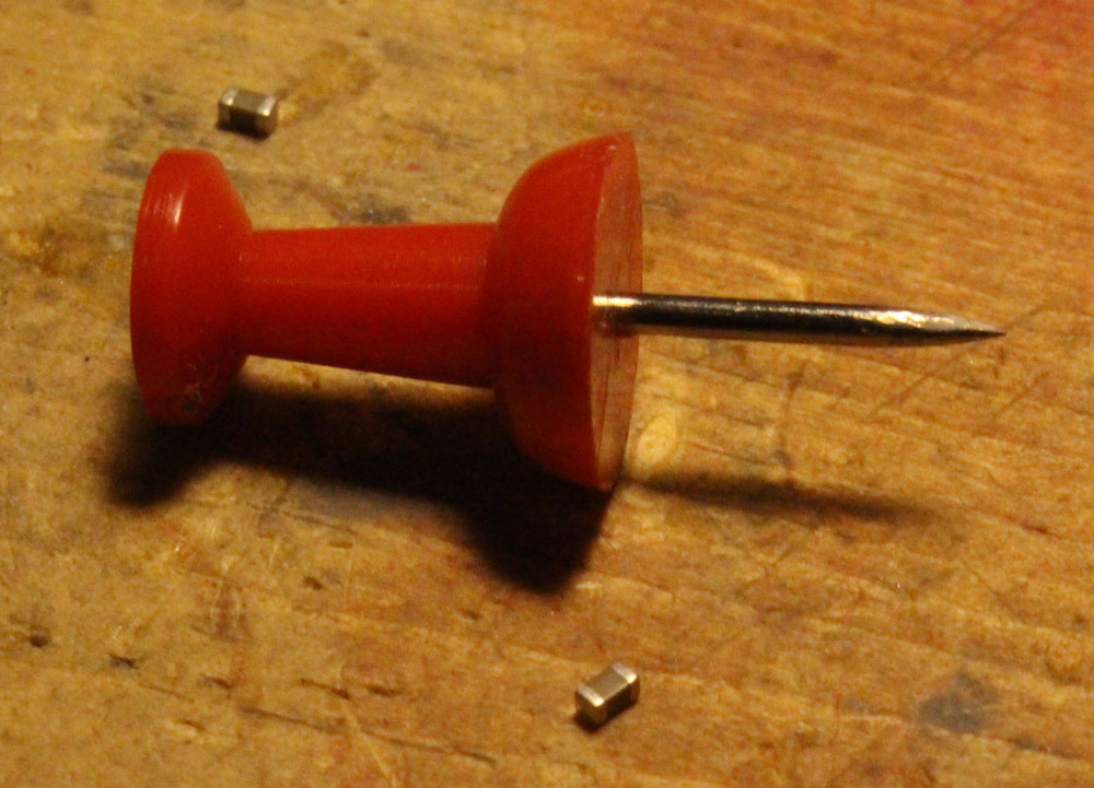
Before you decide to hand solder 0603 capacitors on your board……
Before you decide to hand solder 0603 capacitors on your board……
The Problem: The STM32 Blue Pill sometimes dies for no apparent reason. On the PSU, it’s pulling 30mA and then for now apparent reason, the current draw reduces to 10mA (for the power indicator LED, presumably) and the microcontroller appears dead. It only seems to occur when powered from a power supply to the 5V pin. Once it occurs, giving the 3.3V pin power instead appears to do no good.
For some reason, I’ve been able to fix the problem reliability by removing external power and powering the STM32 via the Stlink clone along with the CLK, GND, and IO pins. Voltage SHOULD be voltage in such a situation, but maybe the IO pin has some kind of effect. I’m really not sure. If anyone knows, please pass on why.
I’ve wondered if the problem is some kind of BOR brownout problem, but I haven’t done the work to find out yet. It only seems to happen with the CS32F103C8T6 STM32 Blue Pill clones (which I currently have 9 of I need to burn through and never buy again.)
I need to know the inductance of the traces I’m creating. It’s too slow to use the inductance calculator at All About Circuits. Unfortunately, the equation has any given variable on both the numerator and the denominator. I refuse to invest the brainpower to develop a rule of thumb, so I’m resorting to a table. I swiped their equation and tossed in typical values for trace widths I used in Python.
I wouldn’t use this for anything hyper serious, but if I’m forced to make a 4″ trace, I can quickly see that doubling the width from 0.5mm to 1mm saves me 12nH.
The intuition to be gained from this (and this is probably not a shocker) is that keeping lengths down is a HUGE deal for reducing the inductance of traces. Trace width is a little more interesting. In terms of %, you get much better benefit for wide traces at short distances. At 0.02″, inductance is reduced from 0.171 to 0.075 when switching from 0.01″ traces to outrageous 0.118″ traces. At distances ~4″, you go from 136.978nH with tiny traces to 93nH with enormous traces.
I’m using the JLC2313 stackup so the height of these calculations (distance from trace to ground plane) is 0.1mm.
Length: 0.02 in
Width: 0.01 in ( 0.25 mm ) Inductance: 0.171 nH
Width: 0.02 in ( 0.51 mm ) Inductance: 0.128 nH
Width: 0.03 in ( 0.76 mm ) Inductance: 0.104 nH
Width: 0.039 in ( 0.99 mm ) Inductance: 0.09 nH
Width: 0.049 in ( 1.24 mm ) Inductance: 0.08 nH
Width: 0.059 in ( 1.5 mm ) Inductance: 0.075 nH
Width: 0.118 in ( 3.0 mm ) Inductance: 0.075 nH
Length: 0.039 in
Width: 0.01 in ( 0.25 mm ) Inductance: 0.464 nH
Width: 0.02 in ( 0.51 mm ) Inductance: 0.368 nH
Width: 0.03 in ( 0.76 mm ) Inductance: 0.309 nH
Width: 0.039 in ( 0.99 mm ) Inductance: 0.269 nH
Width: 0.049 in ( 1.24 mm ) Inductance: 0.239 nH
Width: 0.059 in ( 1.5 mm ) Inductance: 0.216 nH
Width: 0.118 in ( 3.0 mm ) Inductance: 0.151 nH
Length: 0.197 in
Width: 0.01 in ( 0.25 mm ) Inductance: 3.868 nH
Width: 0.02 in ( 0.51 mm ) Inductance: 3.34 nH
Width: 0.03 in ( 0.76 mm ) Inductance: 3.003 nH
Width: 0.039 in ( 0.99 mm ) Inductance: 2.756 nH
Width: 0.049 in ( 1.24 mm ) Inductance: 2.563 nH
Width: 0.059 in ( 1.5 mm ) Inductance: 2.404 nH
Width: 0.118 in ( 3.0 mm ) Inductance: 1.81 nH
Length: 0.394 in
Width: 0.01 in ( 0.25 mm ) Inductance: 9.107 nH
Width: 0.02 in ( 0.51 mm ) Inductance: 8.04 nH
Width: 0.03 in ( 0.76 mm ) Inductance: 7.354 nH
Width: 0.039 in ( 0.99 mm ) Inductance: 6.85 nH
Width: 0.049 in ( 1.24 mm ) Inductance: 6.452 nH
Width: 0.059 in ( 1.5 mm ) Inductance: 6.123 nH
Width: 0.118 in ( 3.0 mm ) Inductance: 4.867 nH
Length: 1 in
Width: 0.01 in ( 0.25 mm ) Inductance: 27.842 nH
Width: 0.02 in ( 0.51 mm ) Inductance: 25.116 nH
Width: 0.03 in ( 0.76 mm ) Inductance: 23.357 nH
Width: 0.039 in ( 0.99 mm ) Inductance: 22.059 nH
Width: 0.049 in ( 1.24 mm ) Inductance: 21.03 nH
Width: 0.059 in ( 1.5 mm ) Inductance: 20.178 nH
Width: 0.118 in ( 3.0 mm ) Inductance: 16.885 nH
Length: 1.969 in
Width: 0.01 in ( 0.25 mm ) Inductance: 61.566 nH
Width: 0.02 in ( 0.51 mm ) Inductance: 56.187 nH
Width: 0.03 in ( 0.76 mm ) Inductance: 52.715 nH
Width: 0.039 in ( 0.99 mm ) Inductance: 50.148 nH
Width: 0.049 in ( 1.24 mm ) Inductance: 48.111 nH
Width: 0.059 in ( 1.5 mm ) Inductance: 46.423 nH
Width: 0.118 in ( 3.0 mm ) Inductance: 39.876 nH
Length: 3.937 in
Width: 0.01 in ( 0.25 mm ) Inductance: 136.978 nH
Width: 0.02 in ( 0.51 mm ) Inductance: 126.21 nH
Width: 0.03 in ( 0.76 mm ) Inductance: 119.255 nH
Width: 0.039 in ( 0.99 mm ) Inductance: 114.109 nH
Width: 0.049 in ( 1.24 mm ) Inductance: 110.025 nH
Width: 0.059 in ( 1.5 mm ) Inductance: 106.638 nH
Width: 0.118 in ( 3.0 mm ) Inductance: 93.477 nH
The smooth fading of LEDs is possible, but it’s best to have 16 bits to work with and ditch the linear world.
// My code
dutyCycle = pow(1.03, time_increment);
// Math equivalent
y = 1.03^x
Above is the most interesting piece of code today. dutyCycle for this code is a number from 0 – 65535. (16-bit resolution is (2^16 – 1 = 65535).
I have the time_increment set to 10ms. So, basically, we are going to increase the dutycyle by 3% every 10ms. You’ll see below that I settled on 375 steps with each time taking 10ms. By using a time_increment that is set to increase every X milliseconds, it’s easy to control the speed of the fading.
To get the 1.03 value, I worked backward and shot for a ballpark rating of 400 individual steps of brightness. Why? No idea.
After some playing, I figured out that 1.03^375 = 65156. 375 steps works for me. The big rule is we can’t exceed 65535 or the microcontroller will rollover.
To put it another way, 65535 + 1 = 0 in digital land. It’s no different than any other cyclical process. In military time, if you add another minute to 23:59, you get 00:00.
For our purposes, we didn’t want rollover. We want to smoothly fade the LED up to it’s maximum brightness and then back down.
Much like our ears, eyes have evolved to handle an atrocious level of dynamic range. Such systems play in the world of logs and exponentials (same thing after you flip the graph axis around). It’s one of those scientific marvels that we can make sense of a duty cycle of 65535 and still tell the difference between 500 and 600. In a linear system, we’d have to pick one extreme or the other.
It turned out that the dutyCycle code above spent a ton of time in the bottom region. After 50 increments of time, for example, the duty cycle would be 4 (1.03^50 = approx 4). That’s “off” in terms of LED brightness to my eyes. There’s a solution.
Remember that 1.03^375 = 65156. Technically, this wastes a bit of our headroom. We have 65535 to work with and our problem is we are spending too much time down around 0. The lucky fix is to use an offset much like you may have learned (and forgotten) in Alegebra class.
y = mx + b
This is a linear function, but the idea of “b” is the same. “b” lets us shift our function up our down. We want to shift the whole thing up. To get our “b” I took 65535 – 65156 to get 379. Let’s just say 375 to be conservative.
// New Code
dutyCycle = pow(1.03, time_increment) + 375;
// Math equivalent
y = 1.03^x + 375.
Now the LEDs do what they are supposed to. There is not excessive time spent with the LEDs “off”. So, at time = 0, we end up with a duty cycle of 376. (1 + 375). 376/65535 * 100 = 0.5% actual duty cycle. In reality, this is a brightness of zero. Solved!
#include <Arduino.h>

#define PWM1_pin PA8
#define PWM2_pin PA9
#define PWM3_pin PA10

#define INCREMENTER 100

void CycleA(int pin, int pwm_limit)
{
	int run = 1;
    long timeA = 0;
    int countUp = 1;
    int dutyCycle = 1;
    int time_increment = 0;


  while (run == 1)
  {

    long currentTime = millis();


    if (pin == 1)
    {
      analogWrite(PWM1_pin, dutyCycle);
    }
    if (pin == 2)
    {
      analogWrite(PWM2_pin, dutyCycle);
    }
        if (pin == 3)
    {
      analogWrite(PWM3_pin, dutyCycle);
    }

    if (currentTime - timeA > 10)
    {
      dutyCycle = pow(1.03, time_increment);
      timeA = currentTime;

      if (dutyCycle > pwm_limit)
      {
        delay(2750);
        //dutyCycle = 1;
        //time_increment = 0;
        countUp = 0;
      }

      if (dutyCycle < 10 && countUp == 0)
      {
        countUp = 1;
        run = 0;
      }

      if (countUp == 1)
      {
        time_increment++;
      }
      else
      {
        time_increment--;
      }
    }
  }
}

void setup()
{

// All PWM pins need to be set as output
// Note:  I've seen multiple examples in which the PWM pins were set to "PWM" instead of "OUTPUT".  I have no explanation for that other than maybe they are using
// the other guy's STM32-to-Arduino library.
  pinMode(PWM1_pin, OUTPUT);
  pinMode(PWM2_pin, OUTPUT);
  pinMode(PWM3_pin, OUTPUT);

  // Change the analogWrite function to operate at 16-bit.  It maxes out at 65535 instead of the 255 of 8-bit.
  analogWriteResolution(16);

}

void loop()
{
 // CycleA(  pin_number,  duty_cycle_limit).
 // This function allows selecting a pin number and sets the duty cycle limit on a scale of 0-65535.
 //  You'll see below that the 10000 for LED Color #1 is there because this was an LED strip that was exceedingly bright.
 //  Basically, the duty_cycle_limit is a brightness limiter.

 // I didn't take the time to pass the pin define (PA8, PA9, and PA10) through a function.

 // Run LED Sequence for LED Color #1
  CycleA(1, 10000);

  // Run LED Sequence for LED Color #2
  CycleA(2, 65000);

  // Red LED Sequence for LED Color #3.
  CycleA(3, 65000);
}
SMD is cooler….when a machine does all the work. At the prototyping phase (and assuming you don’t have all the fancier tools specific to the tiny world of SMD), SMD parts take longer to solder, often require a heat gun to remove, and offer no convenient place to hook your oscilloscope probe to. Bodge wires with any hint of durability are much more difficult and time-consuming in SMD land. In short, compared to thru-hole resistors, SMD resistors are a total pain if a person is engaged in an epic battle. If your battle isn’t all that epic, it won’t matter, but who the hell meddles with non-epic battles?
I learned this the hard way in my senior Capstone project back in engineering school. I had a 100mm x 100mm PCB board with a gigazillion components on it. We used a simple voltage divider before an op-amp to scale our voltage for reading with an ADC. All I had to do was swap out 2 resistors to accommodate us moving up to a much larger voltage. This is something that would have taken me 1-2 minutes if I had all the right tools and 2-3 minutes almost the right tools with thru-hole. My school wasn’t equipped for SMD parts. I had to bring in my heat gun from home. Because the board layout was so tight, even with plenty of Kapton tape to protect the good components, I ended up blowing off 4 or 5 extra components off the board. (I was in a rush. That didn’t help.) Of course, these were specific SMD components and I was crawling around the floor looking for them. In the end, the whole mess could have been avoided if I had just used thru-hole resistors.
Obviously, most of the best chips these days are SMD and many of them offer no DIP-style thru-hole option. In those cases, I’ll gladly use the SMD chip and then break it out with 2.54mm header pins and such to allow for maximum protectivity in battle.