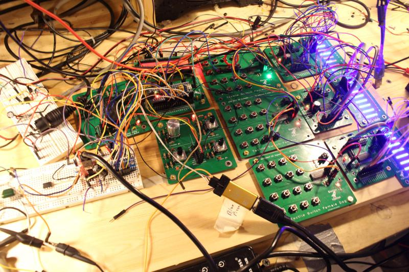
#003 – Raspberry PI Pico vs Blue Pill

Last week I raved at just how much I love the STM32 Blue Pill. It’s my favorite microcontroller! Well, we have a new contender. Will the Raspberry PI Pico knock the STM32 Blue Pill from its pedestal? Find out in another action-packed Electron Injection Podcast episode. (rolled eyes)

#002 – Arduino Uno Killer – STM32 Blue Pill

The STM32 Blue Pill is nothing new, but it may be new to you. In my view, fans of the Arduino Uno are missing out. There are numerous downsides to the Arduino Uno: no debugger, slow performance, and many others I discuss here. The STM32 Blue Pill ain’t perfect, though. It’s got a too-good-to-be-true price, which is actually a problem. I’ll talk about all of that, the fun of getting burned with a soldering iron, the need to shut off the voices in your head when getting your butt kicked by any formidable task.

Posted on Leave a comment

MIDI Test Code on Arduino and STM32 Blue Pill

This code turns the onboard PC13 LED of the STM32 Blue Pill on when a MIDI NoteOn message is received and turns the LED off when a MIDI Noteoff message is received. It’s my preferred way to confirm that a MIDI circuit is working. It relies on the Arduino MIDI Library.

#include <MIDI.h>

#define LED PC13 // LED pin on Arduino Uno

MIDI_CREATE_DEFAULT_INSTANCE();

void doSomeStuffWithNoteOn(byte channel, byte pitch, byte velocity);
void NoteOff(byte channel, byte note, byte velocity);

void setup()
{
  pinMode(LED, OUTPUT);
  MIDI.begin();
  MIDI.setHandleNoteOn(doSomeStuffWithNoteOn);
  MIDI.setHandleNoteOff(NoteOff);
}

void loop()
{

  MIDI.read();
}

void doSomeStuffWithNoteOn(byte channel, byte pitch, byte velocity)
{
  // note on code goes here
  digitalWrite(PC13, LOW);
}

void NoteOff(byte channel, byte note, byte velocity)
{
  // note off code goes here
  digitalWrite(PC13, HIGH);
}
Posted on Leave a comment

Blue Pill STM32 Clones Brown Out or Become Unresponsive

The Problem:  The STM32 Blue Pill sometimes dies for no apparent reason.  On the PSU, it’s pulling 30mA and then for now apparent reason, the current draw reduces to 10mA (for the power indicator LED, presumably) and the microcontroller appears dead.  It only seems to occur when powered from a power supply to the 5V pin.   Once it occurs, giving the 3.3V pin power instead appears to do no good.

For some reason, I’ve been able to fix the problem reliability by removing external power and powering the STM32 via the Stlink clone along with the CLK, GND, and IO pins.  Voltage SHOULD be voltage in such a situation, but maybe the IO pin has some kind of effect.  I’m really not sure.  If anyone knows, please pass on why.

I’ve wondered if the problem is some kind of BOR brownout problem, but I haven’t done the work to find out yet.  It only seems to happen with the CS32F103C8T6 STM32 Blue Pill clones (which I currently have 9 of I need to burn through and never buy again.)


Posted on Leave a comment

Smooth Fading LEDs With STM32 Blue Pill on Arduino Platform

The smooth fading of LEDs is possible, but it’s best to have 16 bits to work with and ditch the linear world.

// My code
dutyCycle = pow(1.03, time_increment);

// Math equivalent
y = 1.03^x

Above is the most interesting piece of code today. dutyCycle for this code is a number from 0 – 65535. (16-bit resolution is (2^16 – 1 = 65535).

I have the time_increment set to 10ms. So, basically, we are going to increase the dutycyle by 3% every 10ms. You’ll see below that I settled on 375 steps with each time taking 10ms. By using a time_increment that is set to increase every X milliseconds, it’s easy to control the speed of the fading.

WHY 1.03?

To get the 1.03 value, I worked backward and shot for a ballpark rating of 400 individual steps of brightness. Why? No idea.
After some playing, I figured out that 1.03^375 = 65156. 375 steps works for me. The big rule is we can’t exceed 65535 or the microcontroller will rollover.
To put it another way, 65535 + 1 = 0 in digital land. It’s no different than any other cyclical process. In military time, if you add another minute to 23:59, you get 00:00.
For our purposes, we didn’t want rollover. We want to smoothly fade the LED up to it’s maximum brightness and then back down.

WHY NOT LINEAR?

Much like our ears, eyes have evolved to handle an atrocious level of dynamic range. Such systems play in the world of logs and exponentials (same thing after you flip the graph axis around). It’s one of those scientific marvels that we can make sense of a duty cycle of 65535 and still tell the difference between 500 and 600. In a linear system, we’d have to pick one extreme or the other.

MAKE IT BETTER

It turned out that the dutyCycle code above spent a ton of time in the bottom region. After 50 increments of time, for example, the duty cycle would be 4  (1.03^50 = approx 4). That’s “off” in terms of LED brightness to my eyes. There’s a solution.

Remember that 1.03^375 = 65156. Technically, this wastes a bit of our headroom. We have 65535 to work with and our problem is we are spending too much time down around 0. The lucky fix is to use an offset much like you may have learned (and forgotten) in Alegebra class.

y = mx + b

This is a linear function, but the idea of “b” is the same.  “b” lets us shift our function up our down. We want to shift the whole thing up.   To get our “b” I took 65535 – 65156 to get 379. Let’s just say 375 to be conservative.

// New Code
dutyCycle = pow(1.03, time_increment) + 375;

// Math equivalent
y = 1.03^x + 375.

Now the LEDs do what they are supposed to.  There is not excessive time spent with the LEDs “off”.    So, at time = 0, we end up with a duty cycle of 376. (1 + 375). 376/65535 * 100 = 0.5% actual duty cycle. In reality, this is a brightness of zero. Solved!


#include <Arduino.h>

#define PWM1_pin PA8
#define PWM2_pin PA9
#define PWM3_pin PA10

#define INCREMENTER 100

void CycleA(int pin, int pwm_limit)
{
	int run = 1;
    long timeA = 0;
    int countUp = 1;
    int dutyCycle = 1;
    int time_increment = 0;
    

  while (run == 1)
  {
     
    long currentTime = millis();


    if (pin == 1)
    {
      analogWrite(PWM1_pin, dutyCycle);
    }
    if (pin == 2)
    {
      analogWrite(PWM2_pin, dutyCycle);
    }
        if (pin == 3)
    {
      analogWrite(PWM3_pin, dutyCycle);
    }

    if (currentTime - timeA > 10)
    {
      dutyCycle = pow(1.03, time_increment);
      timeA = currentTime;

      if (dutyCycle > pwm_limit)
      {
        delay(2750);
        //dutyCycle = 1;
        //time_increment = 0;
        countUp = 0;
      }

      if (dutyCycle < 10 && countUp == 0)
      {
        countUp = 1;
        run = 0;
      }

      if (countUp == 1)
      {
        time_increment++;
      }
      else
      {
        time_increment--;
      }
    }
  }
}

void setup()
{

// All PWM pins need to be set as output
// Note:  I've seen multiple examples in which the PWM pins were set to "PWM" instead of "OUTPUT".  I have no explanation for that other than maybe they are using 
// the other guy's STM32-to-Arduino library.
  pinMode(PWM1_pin, OUTPUT);
  pinMode(PWM2_pin, OUTPUT);
  pinMode(PWM3_pin, OUTPUT);
  
  // Change the analogWrite function to operate at 16-bit.  It maxes out at 65535 instead of the 255 of 8-bit.
  analogWriteResolution(16);

}

void loop()
{
 // CycleA(  pin_number,  duty_cycle_limit).
 // This function allows selecting a pin number and sets the duty cycle limit on a scale of 0-65535.
 //  You'll see below that the 10000 for LED Color #1 is there because this was an LED strip that was exceedingly bright.
 //  Basically, the duty_cycle_limit is a brightness limiter.
 
 // I didn't take the time to pass the pin define (PA8, PA9, and PA10) through a function.
 
 // Run LED Sequence for LED Color #1
  CycleA(1, 10000);
  
  // Run LED Sequence for LED Color #2
  CycleA(2, 65000);
  
  // Red LED Sequence for LED Color #3.
  CycleA(3, 65000);
}