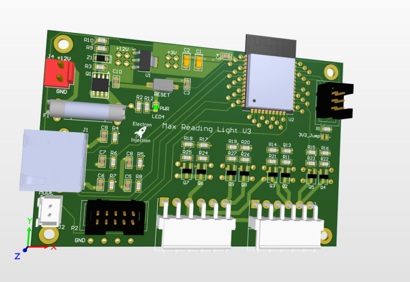
Posted on Leave a comment

Arduino: Transmit 10-bit ADC Reading Through Serial

So the standard Serial.write() or Serial.print in Arduino land is 8-bit All this really means is we need to send one byte ( bits) at a time. If we try to send 10 bits, then bad things happen.

On top of that, it’s better to setup a secret word for start and another one for end. This is the same thing that naked couples do when they get out the power tools. They need safe words. Maybe we all do. Anyhow, by telling our receiver not to bother receiving until it hears the start word and not to finish until it hears the end word, we can be much more confident that the data we are receiving is legit.

A good chunk of this code was taken from various sources from this article. https://forum.arduino.cc/t/serial-input-basics-updated/382007/3

Sending

// Uses ATmega4808  (Thunder Magnum dev board)
#include <Arduino.h>

#define LEDPIN PIN_PA7
#define LEDPIN2 PIN_PA6

int sensorValue;
int newsensorValue;

#define MONITOR_SPEED 115200
void setup()
{
  // put your setup code here, to run once:
  pinMode(LEDPIN, OUTPUT);

  // Setup serial with 2nd ucontroller
  Serial.begin(MONITOR_SPEED); // PA0 is tx and PA1 is rx

  // Setup serial with computer
  Serial1.begin(MONITOR_SPEED); // PC0 is tx.   PC1 is rx.
}

void loop()
{

  // 10 bit ADC read
  newsensorValue = analogRead(PIN_PD0);

  // throw away the lowest 8 bytes to send just the biggest 2 bits
  int Bigbyte = (newsensorValue >> 8);

  // AND 0b1111111 with ADC read to keep only the lowest 8 bits
  int Littlebyte = newsensorValue & 0xFF;

  // talk to computer com port
  Serial1.print("sending: ");

  // combine back together and talk to computer ( sanity check )
  Serial1.println((Bigbyte << 8) + Littlebyte);

  byte startMarker = 0x3C;
  byte endMarker = 0x3E;

  // Talk to 2nd microcontroller
  Serial.write(startMarker);
  Serial.write(Bigbyte);
  Serial.write(Littlebyte);
  Serial.write(endMarker);

  delay(1000);
}

Receive

// Uses ATmega4808  (Thunder Magnum dev board)
#include <Arduino.h>

#define LEDPIN PIN_PA7
#define LEDPIN2 PIN_PA6

void showNewData();
void recvBytesWithStartEndMarkers();

const byte numBytes = 32;
byte receivedBytes[numBytes];
byte numReceived = 0;

boolean newData = false;

#define MONITOR_SPEED 115200
void setup()
{
  // put your setup code here, to run once:
  pinMode(LEDPIN, OUTPUT);

  Serial.begin(MONITOR_SPEED);  // PA0 is tx and PA1 is rx
  Serial1.begin(MONITOR_SPEED); // PC0 is tx.   PC1 is rx.


  digitalWriteFast(LEDPIN, LOW);
  delay(1000);
}

void loop()
{
  recvBytesWithStartEndMarkers();
  showNewData();
}

void recvBytesWithStartEndMarkers()
{
  static boolean recvInProgress = false;
  static byte ndx = 0;
  byte startMarker = 0x3C;
  byte endMarker = 0x3E;
  byte rb;

  while (Serial.available() > 0 && newData == false)
  {
    rb = Serial.read();
 
    if (recvInProgress == true)
    {
      if (rb != endMarker)
      {
        receivedBytes[ndx] = rb;
        ndx++;
        if (ndx >= numBytes)
        {
          ndx = numBytes - 1;
        }
      }
      else
      {
        receivedBytes[ndx] = '\0'; // terminate the string
        recvInProgress = false;
        numReceived = ndx; // save the number for use when printing
        ndx = 0;
        newData = true;
      }
    }

    else if (rb == startMarker)
    {
      recvInProgress = true;
    }
  }
}

void showNewData()
{
  if (newData == true)
  {
    Serial1.println("Received: ");
 
    int receivedandformatted = (receivedBytes[0] << 8) + receivedBytes[1];
    Serial1.println(receivedandformatted);

    Serial1.println();
    newData = false;
  }

#005: Arduino Programming In Pro Products?

Does the Arduino programming language have any place in professional products? This is a topic that comes up frequently for people that have a cool idea and feel the pull of product design but feel like maybe they are wimping out if they were to choose Arduino over Embedded C. Embedded C certainly has performance benefits, but that comes with costs of its own….TIME! In this podcast, I rant and rave incoherently about when Arduino programming should be used and should not be used when developing a product. I also talk about wool socks, heating pads, and dinosaur eggs.

#001 – The Arduino Programming Language Is Legit

Amongst hobbyists, engineers, and programmers there seems to be a great divide as to the validity of the Arduino Programming language (as seen in the Arduino IDE). To be fair, professional embedded C programmers drop down to the depths of register hell to squeeze every ounce of battery life or performance out of their microcontrollers. People digging the holes always lower the eyebrows at the people in the office. The factors that MIGHT matter for a given project are the speed of development, the efficiency of the code (in CPU cycles), and the compiled size of the code. I argue that for low-volume production (including hobbyist electronics projects) only one of these factors matter and it’s not code efficiency or file size.

Posted on Leave a comment

MIDI Test Code on Arduino and STM32 Blue Pill

This code turns the onboard PC13 LED of the STM32 Blue Pill on when a MIDI NoteOn message is received and turns the LED off when a MIDI Noteoff message is received. It’s my preferred way to confirm that a MIDI circuit is working. It relies on the Arduino MIDI Library.

#include <MIDI.h>

#define LED PC13 // LED pin on Arduino Uno

MIDI_CREATE_DEFAULT_INSTANCE();

void doSomeStuffWithNoteOn(byte channel, byte pitch, byte velocity);
void NoteOff(byte channel, byte note, byte velocity);

void setup()
{
  pinMode(LED, OUTPUT);
  MIDI.begin();
  MIDI.setHandleNoteOn(doSomeStuffWithNoteOn);
  MIDI.setHandleNoteOff(NoteOff);
}

void loop()
{

  MIDI.read();
}

void doSomeStuffWithNoteOn(byte channel, byte pitch, byte velocity)
{
  // note on code goes here
  digitalWrite(PC13, LOW);
}

void NoteOff(byte channel, byte note, byte velocity)
{
  // note off code goes here
  digitalWrite(PC13, HIGH);
}
Posted on Leave a comment

Smooth Fading LEDs With STM32 Blue Pill on Arduino Platform

The smooth fading of LEDs is possible, but it’s best to have 16 bits to work with and ditch the linear world.

// My code
dutyCycle = pow(1.03, time_increment);

// Math equivalent
y = 1.03^x

Above is the most interesting piece of code today. dutyCycle for this code is a number from 0 – 65535. (16-bit resolution is (2^16 – 1 = 65535).

I have the time_increment set to 10ms. So, basically, we are going to increase the dutycyle by 3% every 10ms. You’ll see below that I settled on 375 steps with each time taking 10ms. By using a time_increment that is set to increase every X milliseconds, it’s easy to control the speed of the fading.

WHY 1.03?

To get the 1.03 value, I worked backward and shot for a ballpark rating of 400 individual steps of brightness. Why? No idea.
After some playing, I figured out that 1.03^375 = 65156. 375 steps works for me. The big rule is we can’t exceed 65535 or the microcontroller will rollover.
To put it another way, 65535 + 1 = 0 in digital land. It’s no different than any other cyclical process. In military time, if you add another minute to 23:59, you get 00:00.
For our purposes, we didn’t want rollover. We want to smoothly fade the LED up to it’s maximum brightness and then back down.

WHY NOT LINEAR?

Much like our ears, eyes have evolved to handle an atrocious level of dynamic range. Such systems play in the world of logs and exponentials (same thing after you flip the graph axis around). It’s one of those scientific marvels that we can make sense of a duty cycle of 65535 and still tell the difference between 500 and 600. In a linear system, we’d have to pick one extreme or the other.

MAKE IT BETTER

It turned out that the dutyCycle code above spent a ton of time in the bottom region. After 50 increments of time, for example, the duty cycle would be 4  (1.03^50 = approx 4). That’s “off” in terms of LED brightness to my eyes. There’s a solution.

Remember that 1.03^375 = 65156. Technically, this wastes a bit of our headroom. We have 65535 to work with and our problem is we are spending too much time down around 0. The lucky fix is to use an offset much like you may have learned (and forgotten) in Alegebra class.

y = mx + b

This is a linear function, but the idea of “b” is the same.  “b” lets us shift our function up our down. We want to shift the whole thing up.   To get our “b” I took 65535 – 65156 to get 379. Let’s just say 375 to be conservative.

// New Code
dutyCycle = pow(1.03, time_increment) + 375;

// Math equivalent
y = 1.03^x + 375.

Now the LEDs do what they are supposed to.  There is not excessive time spent with the LEDs “off”.    So, at time = 0, we end up with a duty cycle of 376. (1 + 375). 376/65535 * 100 = 0.5% actual duty cycle. In reality, this is a brightness of zero. Solved!


#include <Arduino.h>

#define PWM1_pin PA8
#define PWM2_pin PA9
#define PWM3_pin PA10

#define INCREMENTER 100

void CycleA(int pin, int pwm_limit)
{
	int run = 1;
    long timeA = 0;
    int countUp = 1;
    int dutyCycle = 1;
    int time_increment = 0;
    

  while (run == 1)
  {
     
    long currentTime = millis();


    if (pin == 1)
    {
      analogWrite(PWM1_pin, dutyCycle);
    }
    if (pin == 2)
    {
      analogWrite(PWM2_pin, dutyCycle);
    }
        if (pin == 3)
    {
      analogWrite(PWM3_pin, dutyCycle);
    }

    if (currentTime - timeA > 10)
    {
      dutyCycle = pow(1.03, time_increment);
      timeA = currentTime;

      if (dutyCycle > pwm_limit)
      {
        delay(2750);
        //dutyCycle = 1;
        //time_increment = 0;
        countUp = 0;
      }

      if (dutyCycle < 10 && countUp == 0)
      {
        countUp = 1;
        run = 0;
      }

      if (countUp == 1)
      {
        time_increment++;
      }
      else
      {
        time_increment--;
      }
    }
  }
}

void setup()
{

// All PWM pins need to be set as output
// Note:  I've seen multiple examples in which the PWM pins were set to "PWM" instead of "OUTPUT".  I have no explanation for that other than maybe they are using 
// the other guy's STM32-to-Arduino library.
  pinMode(PWM1_pin, OUTPUT);
  pinMode(PWM2_pin, OUTPUT);
  pinMode(PWM3_pin, OUTPUT);
  
  // Change the analogWrite function to operate at 16-bit.  It maxes out at 65535 instead of the 255 of 8-bit.
  analogWriteResolution(16);

}

void loop()
{
 // CycleA(  pin_number,  duty_cycle_limit).
 // This function allows selecting a pin number and sets the duty cycle limit on a scale of 0-65535.
 //  You'll see below that the 10000 for LED Color #1 is there because this was an LED strip that was exceedingly bright.
 //  Basically, the duty_cycle_limit is a brightness limiter.
 
 // I didn't take the time to pass the pin define (PA8, PA9, and PA10) through a function.
 
 // Run LED Sequence for LED Color #1
  CycleA(1, 10000);
  
  // Run LED Sequence for LED Color #2
  CycleA(2, 65000);
  
  // Red LED Sequence for LED Color #3.
  CycleA(3, 65000);
}