STM32 HAL – Hard n Fast – Cheat Sheet
Remember all those functions in STM32 HAL you can’t remember? This cheat sheet solves that.
Remember all those functions in STM32 HAL you can’t remember? This cheat sheet solves that.
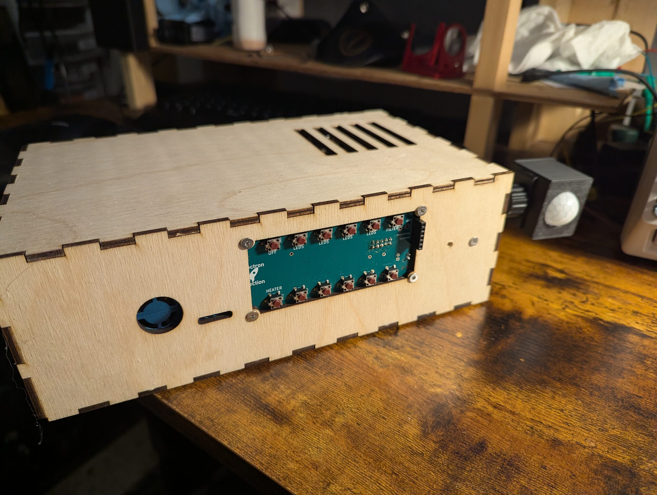
Automation system for my “dungeon”/workshop/lab for automatic handling of lighting, temperature, and air quality.
AutoHotKeys can work with Python and Windows to become a powerhouse tool for automation.
This Python script allows us to clone placement data with an offset to match the placement requirements of a 2×2 array.
This Python script converts an .xlsx Excel file to a .csv files with two clicks. This is useful in times when our tools are designed for .csv files.
This script lists file names and extensions that are unneeded for manufacturing and deletes those files.
This Python script was used to convert a quantity into reference designators.
This Python script allows us to quickly flip the the placement of a .tsv file on either the top, bottom, or both sides and we can flip along either the x-axis or y-axis.
This Python script allows instant importing and exporting of all files through GerbVIO with just a few clicks.
So the standard Serial.write() or Serial.print in Arduino land is 8-bit All this really means is we need to send one byte ( bits) at a time. If we try to send 10 bits, then bad things happen. On top of that, it’s better to setup a secret word for start and another one for … Read more
Here’s a stripped down example of Khoi Hoang’s ESP32TimerInterrupt library. The library claims to run up to 16 compares (or alarms) on one, single timer. It seems to work well although I’ve only tested 3 timers thus far. I plan to use it on my Idiot Christmas Light Controller controlling triacs.
This code turns the onboard PC13 LED of the STM32 Blue Pill on when a MIDI NoteOn message is received and turns the LED off when a MIDI Noteoff message is received. It’s my preferred way to confirm that a MIDI circuit is working. It relies on the Arduino MIDI Library.
The smooth fading of LEDs is possible, but it’s best to have 16 bits to work with and ditch the linear world. // My code dutyCycle = pow(1.03, time_increment); // Math equivalent y = 1.03^x Above is the most interesting piece of code today. dutyCycle for this code is a number from 0 – 65535. … Read more
For the big, bad synth project, I needed an EEPROM. I selected the Microchip 25LC256 from Digikey simply because it had excess capacity (256k) and was thru-hole. (I always recommend this approach when jumping into a new arena of unpolished prototyping). I had never worked with external EEPROM before. It turns out that EEPROM is … Read more
was manually polling my 3 MCP23017 expanders I need for all the buttons for my synth just to get the ball rolling. The serial monitor tells me it was taking almost 5ms….which is similar to the amount of time it’ll take for the dinosaurs to come back. (It’s a billion years in microcontroller land.) I … Read more
Here’s the “Hello World” edition of getting access to USART2 and USART3 on an STM32 Blue Pill in PlatformIO using the Arduino framework. /* lib_deps = NONE # Using a library name ——– Platform.ini Settings———- [env:bluepill_f103c8] platform = ststm32 board = bluepill_f103c8 #board = bluepill_f103c8 framework = arduino upload_protocol = stlink lib_compat_mode = soft */ … Read more
I kept getting values that were way too low when feeding an ADC on the STM32 Blue Pill 3.3V. I should have been getting values that were around 4000 and instead I was closer to 800. Solution 1) The default ADC in the Arduino library is set to 10-bit resolution. This is what you … Read more
I needed a lengthy list of files for a massive 3D printing project I’m starting and I didn’t want to have to copy and paste each file one at a time. Brandon’s Rule #232: If you are faced with a 2 minute task that bores the hell out of you, invest 15 minutes into automating … Read more
I need about 40 buttons for my synth project. I’m trying to run the entire synth with a single STM32 Blue Pill. I’ve already shown how I can run 256 LEDs with 3 pins LINK IT HERE. Since the MCP23017 is I2C, I could possibly run 128 buttons on 2 pins. For now, I’m just … Read more
My boss – okay he’s a professor at school – at my internship – okay, it’s an unsanctioned internship and I’m working for free – asked me to clean up the GUI on a LabVIEW power measurement circuit. I have vast experience with .css from my html background so I thought “no problem”. I’ve debated … Read more
I just spent about 3 hours getting lost in the bottomless toilet that is the Eclipse Preferences menu. For those who are out of the loop, dark themes are like running water and refrigeration. There is no going back to old ways without them. I’d consider ditching the fridge before giving up dark themes. Many … Read more