STM32 HAL – Hard n Fast – Cheat Sheet
Remember all those functions in STM32 HAL you can’t remember? This cheat sheet solves that.
Remember all those functions in STM32 HAL you can’t remember? This cheat sheet solves that.
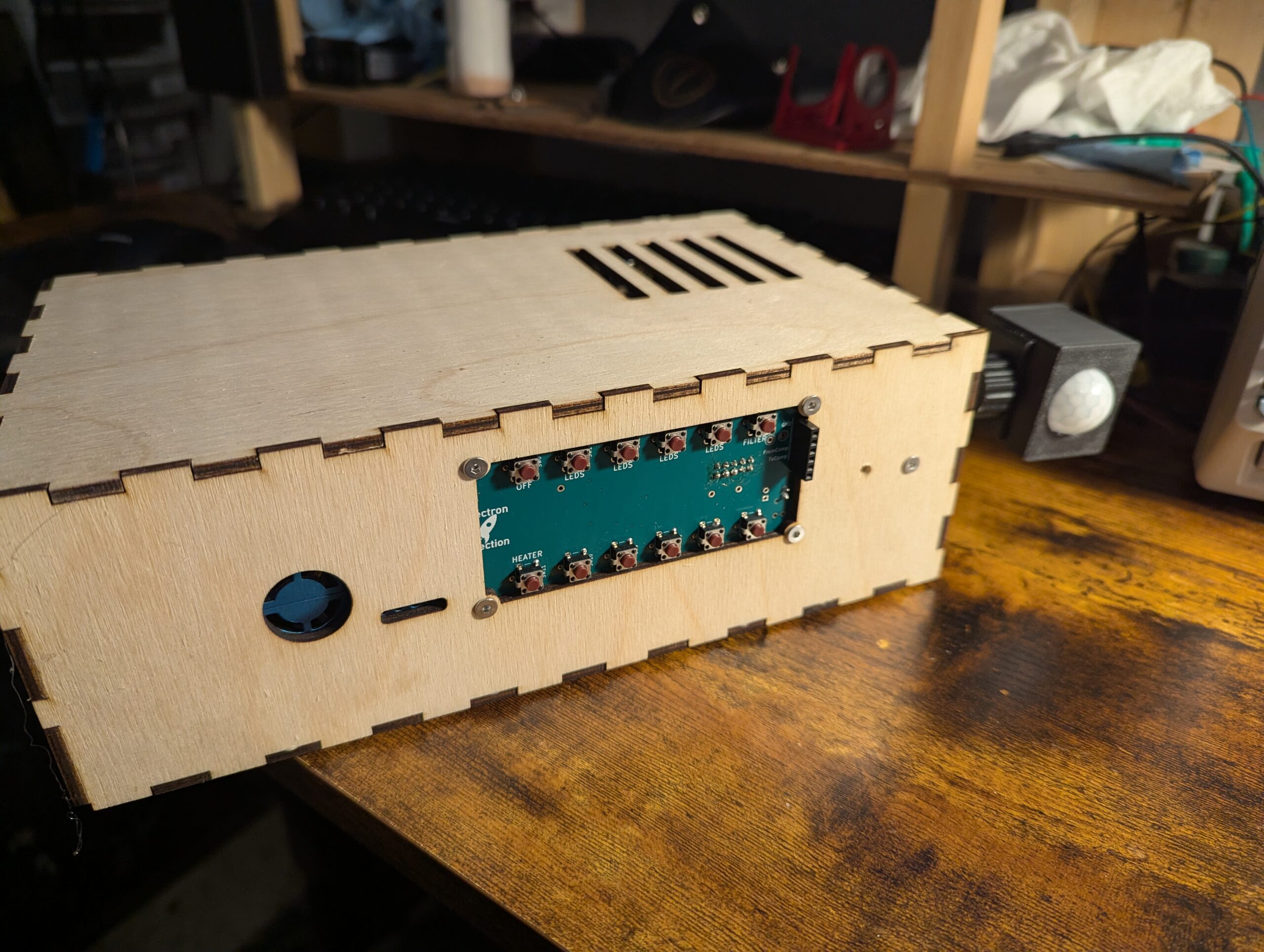
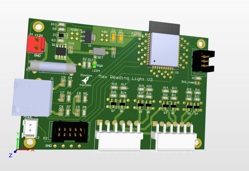
Automation system for my “dungeon”/workshop/lab for automatic handling of lighting, temperature, and air quality.
Griswold may have needed an nuclear power plant for his lights, but his didn’t blink. Not enough.
Believe it or not this is a fully functional music synthesizer with fully every possible parameter tweakable and can save presets. The synth sound horrible, but that was by design. The YM3812 chip is from an old Soundblaster card from back in the Reagan days. This thing sounds like bad dog stuff. It’s so bad … Read more

I became intrigued with the 200W+ audio amplifiers on Amazon for $80 or so on Amazon. I did a little digging and found that some were based on a TI TPA3255 chip. I picked up a few MPN: TPA3255DDV and went to town. I basically lifted this schematic directly from the datasheet so it wasn’t … Read more

The task: Take a DC boost converter controlled with with a PID loop. Input a 60Hz sine wave as the setpoint. This creates a 60Hz sine wave with a DC offset. Make another identical DC boost converter and slam them together across a resistive load. (See schematic). The end result is the DC voltage is … Read more

My friend wanted to control the level of his home stereo system built into his house. No problem. Sorta. I bought an off the shelf Bluetooth audio receiver so phones could send audio to this thing. Ran it through my PCB and split the audio out to a couple of those Class D amplifiers based … Read more
Requirements: This was a basic project. The ESP32 is overkill for this, but I had it on hand. For linear faders that are normally used on a mixing console create voltage dividers that are read by the ADC on the ESP32. The light is dimmed with standard PWM and MOSFETs. Fun artifact. My son wanted … Read more
The world needed another USB 3.1 hub. Nevermind that they can be purchased for the cost of a sugar-laden cup of coffee. I needed this module block for the future and I always like to design these in chunks when I can.

I built a guitar for my son for his birthday. Basswood body, single humbucker in the bridge, super jumbo frets, locking tuners. I used the laser to draw the basic body shape, which I drew in Fusion 360. I basically eyeballed the Solar guitars when drawing the outline in Fusion 360. It’s not exact, by … Read more
AutoHotKeys can work with Python and Windows to become a powerhouse tool for automation.
This Python script allows us to clone placement data with an offset to match the placement requirements of a 2×2 array.
This Python script converts an .xlsx Excel file to a .csv files with two clicks. This is useful in times when our tools are designed for .csv files.
This script lists file names and extensions that are unneeded for manufacturing and deletes those files.
This Python script was used to convert a quantity into reference designators.
This Python script allows us to quickly flip the the placement of a .tsv file on either the top, bottom, or both sides and we can flip along either the x-axis or y-axis.
This Python script allows instant importing and exporting of all files through GerbVIO with just a few clicks.
So the standard Serial.write() or Serial.print in Arduino land is 8-bit All this really means is we need to send one byte ( bits) at a time. If we try to send 10 bits, then bad things happen. On top of that, it’s better to setup a secret word for start and another one for … Read more
I had hell with the drivers for the Atmel ICE to talk to the ATmega4808 so I figured I’d keep my settings here. PlatformIO platformio.ini [env:ATmega4808] platform = atmelmegaavr board = ATmega4808 framework = arduino upload_speed = 115200 upload_protocol = atmelice_updi Device Manager Looks LIke This Zadig Looks Like This
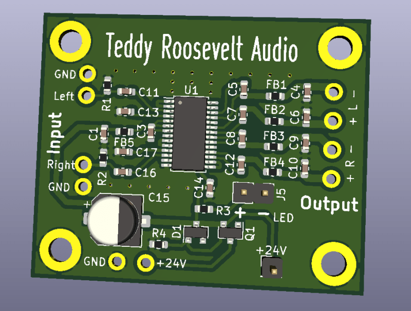
I needed a low power audio amplifier for my home audio setup. Nothing crazy. I basically wanted to match what a car stereo head unit could do. I didn’t want to fiddle with large power and I wanted something cheap. I had done plenty of PCBs for manipulating audio signals, but I had never tried … Read more
The code below will heat the hot end nozzle up to 185 and then set the e-steps to 147.19, and then slowly extrude 100mm of filament. To use it, mark a line 120mm from your extruder on your filament. Run this gcode as if Cura spit it out. Measure the line. You want to be … Read more
Here’s a stripped down example of Khoi Hoang’s ESP32TimerInterrupt library. The library claims to run up to 16 compares (or alarms) on one, single timer. It seems to work well although I’ve only tested 3 timers thus far. I plan to use it on my Idiot Christmas Light Controller controlling triacs.
It takes about 20 seconds to put a potentiometer model in LtSpice. I have no idea why it wasn’t included. Regardless…. — Download the “Pot” folder at https://github.com/brandondrury/LTspice-Libraries — Find your C:\Users\YOUR_USERNAME\Documents\LTspiceXVII\lib\ folder— Place pot.asy in your “sym” folder. C:\Users\YOUR_USERNAME\Documents\LTspiceXVII\lib\sym\— Place pot.sub in your “sub” folder. C:\Users\YOUR_USERNAME\Documents\LTspiceXVII\lib\ sub\— Click the text tool. Select “SPICE Directive” … Read more

