Posted on Leave a comment

Reading Light Bar

Requirements:

  • Diffused RGBW light that is great for reading that can be mounted to the wall
  • Requires different modes of operation. a) Crazy light show b) Adjustable R G B and W light via faders
    • Reading mode should start out at the set brightness and then fade incrementally for an hour until eventually shutting off. You shouldn’t notice the light is getting dimmer.

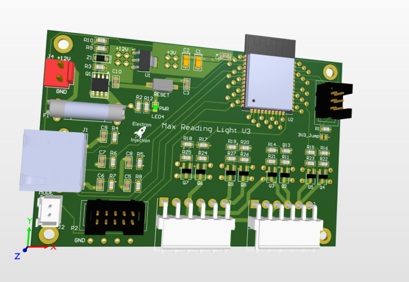
This was a basic project. The ESP32 is overkill for this, but I had it on hand. For linear faders that are normally used on a mixing console create voltage dividers that are read by the ADC on the ESP32. The light is dimmed with standard PWM and MOSFETs. Fun artifact. My son wanted to know why his ceiling fan was spinning backwards. He learned all about aliasing! Fun stuff. The PWM frequency I chose is just a hair faster than the rotation of the fan. Persistence of vision says humans can see light when it blinks fast enough, but tell that to the fan. It knows!

Lessons Learned

I don’t know what I was thinking! I used a linear regulator to step down from 12V to 3.3V. That’ll never happen again. Dissipating 8V+ when an ESP32 is pulling hefty power for a modern microcontroller is a bad, bad idea. I should have used a switching regulator. People worry about the noise. Fair enough. I worry about melting!

Those hefty VM3.96mm connectors at ref des: J5 and J3 are strong. They are also a bit too snug. They are meant to be plugged in and stayed plugged in. That’s good. The problem is if you ever want to take the connector off. They are kinda terrible. Granted, I’m sure I got these from Ali Express for $0.00001. Maybe you get what you pay for sometimes.

This was a fun little project. The greatest challenge was getting the clearance right on the 3D printed “tracks” for the LEDs.

As always I always struggle with wiring and connectors. The NAME OF CONNECTOR GOES HER wasn’t nearly as handy for plugging and unplugging as I had hoped. I used an RJ45 connector for the ESP32 to talk to the fader. That worked well. The lesson is a consumer-approved connector should always be used for “consumer approved tasks” whatever that means.

Posted on Leave a comment

USB 3.1 2-port Hub

The world needed another USB 3.1 hub. Nevermind that they can be purchased for the cost of a sugar-laden cup of coffee. I needed this module block for the future and I always like to design these in chunks when I can.

I chose to design this with parts I could get from Digikey / Mouser. Higher end assembly factories tend to require that and I don’t want to get addicted to insanely cheap parts from LCSC. For a just-for-fun board it doesn’t really matter, I guess.

EDA Tool: Altium Designer

Key Features: 6 layers ( overkill ! ) , 10Gbs digital signals, high speed differential signals.

Experiment #0: I’m new to USB 3.1. 10Gbs is fast for me. The rise time is in the picoseconds (according to Google) and that means I need to focus on signal integrity. I’ve read Signal Integrity and Power Simplified book twice. Luckily, I’ve forgotten most of it and need to read it again. SMILIE

Experiment #1: 0201 – How will JLCPCB handle 0201 passives? No clue. Will it cost a fortune? Probably. I doubt if they are really necessary, but they were recommended by the datasheets so I’m just gonna run with it for now. At the 0201 scale, soldermask dam thickness minimums start to get pushed. This can be overcame with a stencil but it relies on someone paying attention. I’m nervous.

Experiment #2: I’ve always wanted to use TI’s WEBENCH-CIRCUIT-DESIGNER. For some reason it always recommends Texas Instrument switching regulators. I smell bias. For certain passives, it also recommended 0201s. I’m all all for keeping loops tight, but is this really necessary on a wimpy power rail? We’ll see. I followed directions this time. I’ll optimize later.

Experiment #3: MPN: TUSB8020BPHP Why buy a complete 4-power USB hub with enclosure when I can buy just the controller chip for that price!! I’ve never used it before. We’ll see!

I’m going with JLCPCB on this one and using their JLC06161H-2116A Stackup.

Posted on Leave a comment

Arduino: Transmit 10-bit ADC Reading Through Serial

So the standard Serial.write() or Serial.print in Arduino land is 8-bit All this really means is we need to send one byte ( bits) at a time. If we try to send 10 bits, then bad things happen.

On top of that, it’s better to setup a secret word for start and another one for end. This is the same thing that naked couples do when they get out the power tools. They need safe words. Maybe we all do. Anyhow, by telling our receiver not to bother receiving until it hears the start word and not to finish until it hears the end word, we can be much more confident that the data we are receiving is legit.

A good chunk of this code was taken from various sources from this article. https://forum.arduino.cc/t/serial-input-basics-updated/382007/3

Sending

// Uses ATmega4808  (Thunder Magnum dev board)
#include <Arduino.h>

#define LEDPIN PIN_PA7
#define LEDPIN2 PIN_PA6

int sensorValue;
int newsensorValue;

#define MONITOR_SPEED 115200
void setup()
{
  // put your setup code here, to run once:
  pinMode(LEDPIN, OUTPUT);

  // Setup serial with 2nd ucontroller
  Serial.begin(MONITOR_SPEED); // PA0 is tx and PA1 is rx

  // Setup serial with computer
  Serial1.begin(MONITOR_SPEED); // PC0 is tx.   PC1 is rx.
}

void loop()
{

  // 10 bit ADC read
  newsensorValue = analogRead(PIN_PD0);

  // throw away the lowest 8 bytes to send just the biggest 2 bits
  int Bigbyte = (newsensorValue >> 8);

  // AND 0b1111111 with ADC read to keep only the lowest 8 bits
  int Littlebyte = newsensorValue & 0xFF;

  // talk to computer com port
  Serial1.print("sending: ");

  // combine back together and talk to computer ( sanity check )
  Serial1.println((Bigbyte << 8) + Littlebyte);

  byte startMarker = 0x3C;
  byte endMarker = 0x3E;

  // Talk to 2nd microcontroller
  Serial.write(startMarker);
  Serial.write(Bigbyte);
  Serial.write(Littlebyte);
  Serial.write(endMarker);

  delay(1000);
}

Receive

// Uses ATmega4808  (Thunder Magnum dev board)
#include <Arduino.h>

#define LEDPIN PIN_PA7
#define LEDPIN2 PIN_PA6

void showNewData();
void recvBytesWithStartEndMarkers();

const byte numBytes = 32;
byte receivedBytes[numBytes];
byte numReceived = 0;

boolean newData = false;

#define MONITOR_SPEED 115200
void setup()
{
  // put your setup code here, to run once:
  pinMode(LEDPIN, OUTPUT);

  Serial.begin(MONITOR_SPEED);  // PA0 is tx and PA1 is rx
  Serial1.begin(MONITOR_SPEED); // PC0 is tx.   PC1 is rx.


  digitalWriteFast(LEDPIN, LOW);
  delay(1000);
}

void loop()
{
  recvBytesWithStartEndMarkers();
  showNewData();
}

void recvBytesWithStartEndMarkers()
{
  static boolean recvInProgress = false;
  static byte ndx = 0;
  byte startMarker = 0x3C;
  byte endMarker = 0x3E;
  byte rb;

  while (Serial.available() > 0 && newData == false)
  {
    rb = Serial.read();
 
    if (recvInProgress == true)
    {
      if (rb != endMarker)
      {
        receivedBytes[ndx] = rb;
        ndx++;
        if (ndx >= numBytes)
        {
          ndx = numBytes - 1;
        }
      }
      else
      {
        receivedBytes[ndx] = '\0'; // terminate the string
        recvInProgress = false;
        numReceived = ndx; // save the number for use when printing
        ndx = 0;
        newData = true;
      }
    }

    else if (rb == startMarker)
    {
      recvInProgress = true;
    }
  }
}

void showNewData()
{
  if (newData == true)
  {
    Serial1.println("Received: ");
 
    int receivedandformatted = (receivedBytes[0] << 8) + receivedBytes[1];
    Serial1.println(receivedandformatted);

    Serial1.println();
    newData = false;
  }
Posted on Leave a comment

Low Power Audio Amplifier

I needed a low power audio amplifier for my home audio setup. Nothing crazy. I basically wanted to match what a car stereo head unit could do. I didn’t want to fiddle with large power and I wanted something cheap. I had done plenty of PCBs for manipulating audio signals, but I had never tried an audio power amplifier before. Granted, this one is a baby, but it was a great way to get my feet wet cheaply.

I’ve used this audio amplifier every day for maybe 4 years. Great little gadget! No issues. Much like a car stereo, it surprises people how loud it is until it runs out of power when you need it and distorts all to hell.

No Markings?

Notice the input on the silkscreen has no instructions. Ahhhh! I would never do that now. I’d list the exact voltage and maybe current requirements right on the silkscreen for a board like this. I’d probably list the min speaker impedance on the outputs as well.

Old Kicad – No Ground Plane?

I’m 99% sure I used a ground plane on this thing. I can’t imagine a world where I wouldn’t have. However, and this is one of the problems with Kicad, when you open a project 4 years later with a different Kicad version, strange things can happen. I opened the .kicad_pcb file in Notepad++ and now I see I used Kicad 5.1.9 to design this board. (Human-editable files is a HUGE benefit to Kicad, btw.) Do I still have it on my computer? Maybe. I don’t plan on producing any more so it doesn’t matter.

Main Audio Chip. MPN: IS31AP2112 (Discontinued).

EDA Tool: Kicad

If you are interesting in the files, contact me. These files aren’t up to my modern standards, but I’ll share them to anyone who asks. I mostly just followed the datasheet examples, but there may be some clues in here that worked in the supporting circuitry.