Posted on Leave a comment

Idiot Christmas Light Controller

There are 3 types of people at Christmas time. People that put up:

  • A reasonable amount of Christmas lights
  • No Christmas Lights at all
  • An ungodly horrendous amount of Christmas lights.

I’m the third type.

I decided the world needed a box with 8 outlets that could be controlled from a master in my house. I wanted the ability to dim the lights, blink the lights, control the lights with DMX down the road ( never did that one ), but ultimately decided all I really needed was to blink them in the most chaotic way possible. Random was good as long as half the lights were on at any given time. Completely random blinking meant that half the lights were off about half the time. About 25% of the time only 25% of the lights were on. I didn’t like that.

Oh, and I made 8 boxes. So that’s 64 outlets total.

Too keep the current consumption reasonable, I decided that not only was 4 outlets the minimum number outlets, it’s the perfect amount of lights that should be on. It’s totally random which 4 outlets are on for each box, but it is only four.

Running power all over the yard was made simpler by allowing 110VAC input and output on every box.

This project consisted of:

  • A TRIAC power board x8
  • A Receiver board x8
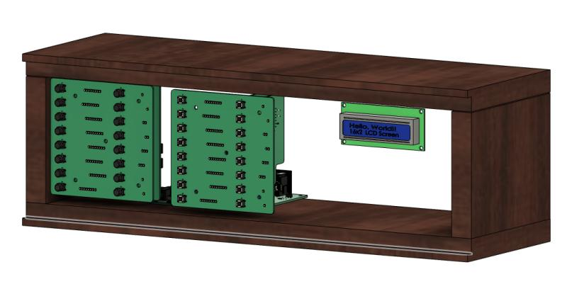
  • 3D printed customer enclosure x8
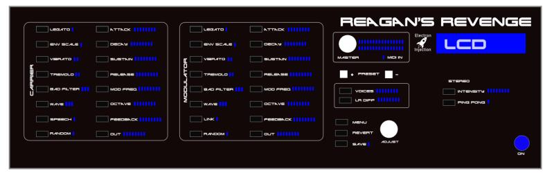
  • A control board

ESP32

My weapon of choice whenever wireless or wi-fi is being used is the ESP32. I have many of the cheapo Ali Express Dev boards, but I spun my own boards for this one. Wireless range was a concern, but the ESP-NOW library allowed me to build up a mesh network so that each ESP32 board could talk to the other one. The library does all the heavy lifting, but range has been no problem at all even though my control board is down in a basement.

TRIAC Board

TRIAC Board

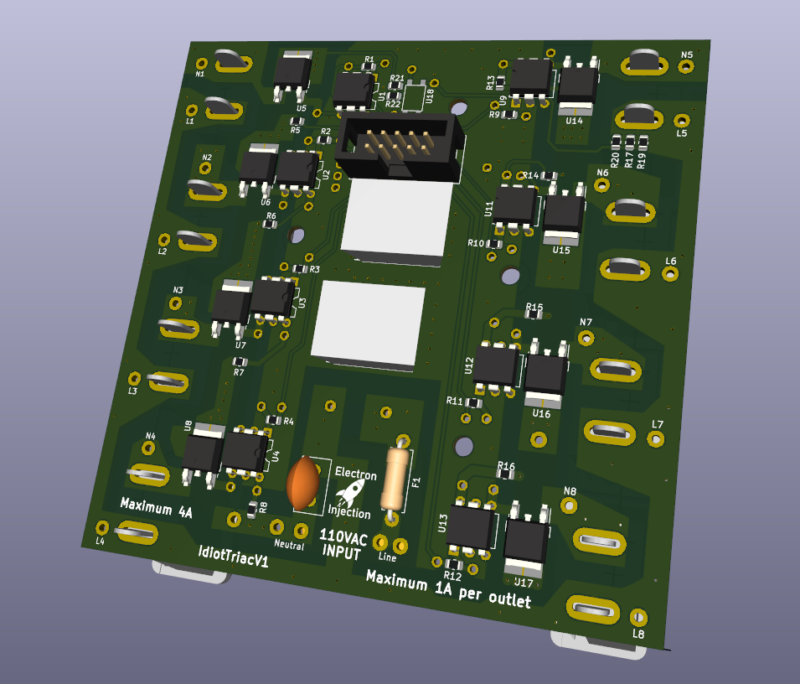
I guess you can call this a mixed signal board. It’s not EXACTLY a digital signal, but there is some 110VAC power here….at least by my standards. Each outlet is rated for 1A (20 strands of lights), but I’ve never came close to that number. The board itself is rated at 4A total, but I need to check my old notes to see how I came up with that.

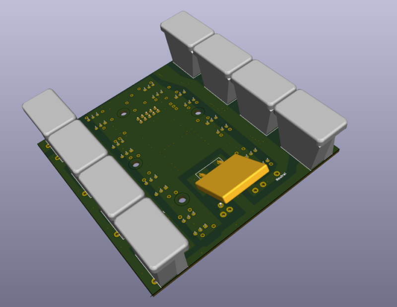
The bottom pick is missing the slots where the Christmas Lights plug into. It makes much more sense with that correction. I took a chance on this approach. This 3D model does not show the enclosure the outlets must slip through before soldering. Luckily, this approach has been bulletproof for 5 years and allowed me to avoid wires. Life doesn’t get much better than avoiding wires.
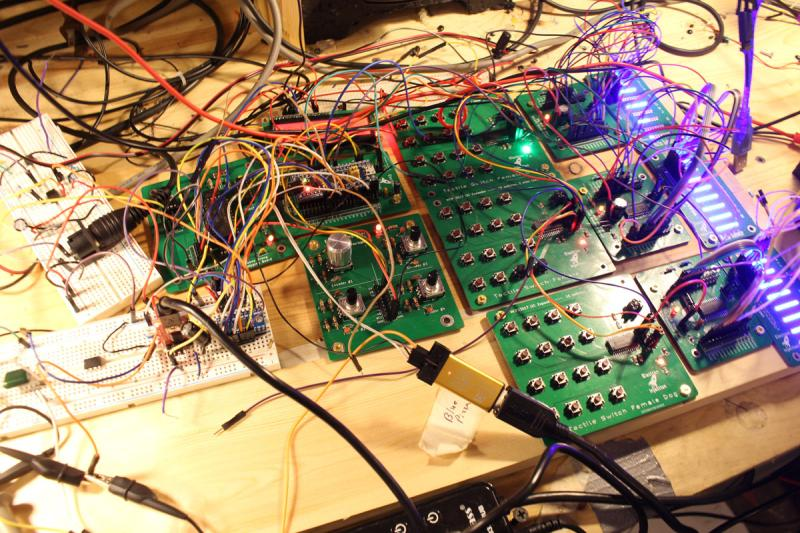
Receiver Board

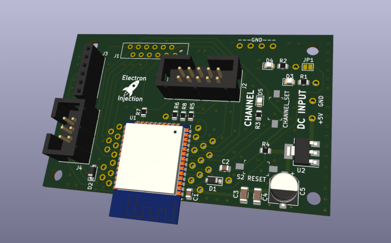
This receiver board is super simple. +5V input. The ESP32 talks to the Sender via ESP-NOW (more or less wi-fi, kinda). It talks to the TRIAC board via the IDC connector. I originally designed this using a press fit connector instead of the IDC connector. Lesson learned. See “Mistake” below.

Mistakes

Press Fit Connectors Without Serious Jig = Bla!

I experimented with a ribbon connector to mate the TRIAC board with the receiver board within each box. I found some new connectors where you just smash the ribbon with these jaws-of-life teeth. These are probably great if you have a jig to correctly smash them. (I later learned all about press fit connectors at work.) My “jig” was completely inadequate and some of the connections were bad. I lost one or two outlets on each box right away and had to redo the press fit process over and over to get it right. Even then, the connection was unrliable.

I could have used standard 2×5 IDC 2.54mm cables. I always have dozens on hand. I guess my need to experiment bit me that time.

The press fit style connector can not be taken off and this made troubleshooting difficult at times. Lesson learned.

If I redesigned this, I’d use a board-to-board connector…probably just standard 2.54mm headers.

Strengths

PETG Works Great For Enclosures!

PETG enclosures have been very durable. I left 2 of these boxes outside. They are covered to keep the rain out, but nothing else. In a bad storm, they’ll get wet. They’ve been outside since October 2021. They still work very well.

Modern LED Christmas Lights Use Little Power

I’m not sure I believe it, but a 25ft strand of the LED Christmas Lights I purchased only consumes 50mA….and they are really too bright. I’ve considered knocking the brightness down in the code by shortening the TRIAC “duty cycle”. I don’t that’s the term when dealing with TRIACS but this project was 5 years ago and it is the term for PWM and the concept is mostly the same.

Enclosure Ventilation Is Good

Everyone says that water and electronics don’t mix. That’s super true if you’ve got an electrolyte in your water. What they don’t tell you is humidity is everywhere ( not a shock ) and no matter how well you seal up your enclosure, water vapor is getting in. In December in Missouri the temperatures will get down to 0F sometimes and as high as 70F with a typical temperature at any given time being around 32F. That’s a recipe for condensation.

So even if you think you completely sealed your enclosure, water vapor is getting in and that moisture is going to experience condensation. Then you have water….not jus t the vapor in your enclosure. If you think you sealed the water out, you’ve now just sealed the water in. OUCH! That part isn’t intuitive.

I took ventilation seriously and it’s paid off tremendously.

Posted on Leave a comment

YM3812 Synthesizer

Believe it or not this is a fully functional music synthesizer with fully every possible parameter tweakable and can save presets. The synth sound horrible, but that was by design.

The YM3812 chip is from an old Soundblaster card from back in the Reagan days. This thing sounds like bad dog stuff. It’s so bad it’s fun. I fell in love with this little SPI chip. Designing a full blown synthesizer with hardware interface ended up being a fairly atrocious amount of work, but I was graduated and unemployed. The intention was to take what started out as an Arduino project and move into a legit project.

I ran into problems with this one on the mechanical side. I needed a way for buttons to feel “good” and I needed a user interface that felt sturdy….like I could throw it down the stairs and it not break. Of all theory of magnetic fields and high speed signal propagation I have studied, I had no background in making a product tough. So this is a fully functional synthesizer that worked in prototype mode, but by the time of V2 I was bogged down by the mechanical end and working a full time job. Eventually, it was out of sight and out of mind. I would love to go back now and slaughter this one.

Microcontroller: STM32 Blue Pill

I was really into these STM32 Blue Pills in 2020. They provided tons of bang for the buck, got me into Cortex M3 32-bit land, and were a big step up from the Atmega328p microcontrollers in the Arduino clones I had laying around. The price was basically the same. I ended up ditching the Cortex M3 because when it came time to design PCBs without modules, the MPN: STM32F103C8T6 was very expensive and had a lead time of a billion years due to the supply chain nasties that didn’t really go away until 2023 or so.

2020 = Mechanically Awful!

When I got my job at Macrofab as a “circuit board analyzer”, I had not studied many products for how to “do it”. I was coming from 4 years of aggressive Arduino hobbyist work followed by 4 years of hell in school and trying to put it all together. You can see that here. I just used a 3/4″ wooden box with butt joints as my “enclosure”. It’s one way to do it, but it’s a dumb way.

You can see from this rear view how much empty space I was working with. Granted, for this phase of the prototype it didn’t matter. I was experimenting with board-to-board connections using 2.54mm which was definitely the right track.

Looking at the front with the pretty cover removed, you could see I had 2 PCBs for the switches. This strikes me as expensive at the moment, but I say that about air, too. These front panel PCBs contained the switches but also contained the LEDs that were used to indicate the level/intensity/setting of every possible parameter on the synths.

It makes more sense if you look at what I had planned for the front panel. This would have been a 3U rack, if I remember correctly. My gut says this is a $1,000 product when I look at it. I had temptations to do all of this GUI stuff on a $70 tablet and call it a day. Talk to the main microcontroller through UART / bluetooth / wifi / whatever. That approach would have been radically cheaper.

Below is the money shot.

On the far left breadboards you can see old-school MIDI inputs. Just to the right of that is the actual YM3812 audio circuit. I’m trying to remember if I had 2 of these. I believe I did so that I could have more voices. You could argue the point using a primitive junk 80’s chip is to be limited, but my brain doesn’t work that way. I wanted the brain to be awesome. With more voices, I could detune one chip slightly and that allows for all kinds of big, nasty sounds one may hear in supersaw dance land.

Below the 2 YM2812 synth boards is an encoder PCB. It has 4 encoders but I was only using one or two of them. I had built that as a development tool back in the day and got plenty of use out of it on the breadboard.

To the right you can see the PCBs with 16 switches each. These, too, were prototype tools I developed. I need to look up the chip. I used a SPI expander so that I could have a ton of buttons with only only the CS, MOSI, MISO traces.

To the left of that was the TM1640 LED drivers. I need to look up how I drove these LEDs. Now I don’t remember and I’d like to pick my brain. I may have put real thought into this and came up with an interesting solution. I bet I came up with a matrix array thing. I’m not sure how I’d have enough IO otherwise.

On the far right, you can see the blue LEDs that were used to indicate level.

Posted on Leave a comment

Big Girl Audio – Audio Power Amplifier

I became intrigued with the 200W+ audio amplifiers on Amazon for $80 or so on Amazon. I did a little digging and found that some were based on a TI TPA3255 chip. I picked up a few MPN: TPA3255DDV and went to town. I basically lifted this schematic directly from the datasheet so it wasn’t like I had to get super creative, but it was fun dealing with power levels that I’m not used to.

This one worked on the first try, so you know something went very wrong. The difference is this time I don’t know what it was. Maybe that’s the definition of success.

Posted on Leave a comment

POWER INVERTER IN DQ REFERENCE FRAME

The task: Take a DC boost converter controlled with with a PID loop. Input a 60Hz sine wave as the setpoint. This creates a 60Hz sine wave with a DC offset. Make another identical DC boost converter and slam them together across a resistive load. (See schematic). The end result is the DC voltage is cancelled out and the AC voltage is multiplied by 2.

I don’t like talking about this one. I was sprinting full speed for months. The goal: Get my electronics project in a peer-reviewed journal before I graduated from engineering school. I was on a mission and it was going to work. I had managed to take a 5V DC signal and crank it up to 41VAC RMS. The goal was 120VAC.

I had problems with a massive inductive spike on startup that confused the heck out of the PID loop to the point that I could never get the thing to start correctly. Damn causal systems! I created a massive capacitor bank to counter the massive inductive spike.

Then that stupid pandemic thing happened in 2020. I lost access to the university’s high end power supply needed to get this bird off the ground. In addition to a full load of senior engineering classes I was now spending 6 hours a day trying to convince a GRUMPY GRUMPY GRUMPY first grader to do his homework with me. (At-home learning works well….WHEN DONE CORRECTLY…but not for the little ones.)

I bought a 48V DC Meanwell PSU like you see for servers and such. I tried getting this to work at home. Working 18 hours a day pre-Pandemic was possible. My role as a father (and now first grade teacher) was not compatible. I chose to be a good dad. It stung. While comedians all over the world were endlessly ranting about their Netflix binges and ping pong table purchases, I was working myself beyond the absolute maximum and it wasn’t enough.


Posted on Leave a comment

Remote Audio Level Control

My friend wanted to control the level of his home stereo system built into his house. No problem. Sorta.

I bought an off the shelf Bluetooth audio receiver, ran that through this Remote Audio Level Control box. The box is USB powered. I used XXXXXXXXXXXX I2C digital potentiometers to control the level. I used a XXXXXXXXXX microcontroller. My friend is crazy and refused to use wifi….even though he’ll be streaming his music from Spotify. Okie dokie. Challenge accepted.

It turned out I needed a second board to be mounted in the 2-gang panel outlet. It measured the level of the standard potentiometers on the wall and checked the state of 2 switches. My friend is also crazy and wanted to be able to cut power to the amplifiers when not in use. So the 2 switches control relays to the audio power amplifiers.

I really wanted this thing to last 15+ years and I was concerned about scratchy pots. I wasn’t exactly sure how long the cable from from the panel on the wall was going to be to the amplifiers. So, I decided to put a XXXXXXXXXXX microcontroller in the wall and send a UART signal to the controller on the audio level board. This worked out pretty well.

Problem #1: I used Fosi amplifiers from Amazon. These use a TI TPXXXXXXXX chip for impressive efficiency in audio power land. I’ve built one very similar. When power is cut to the amplifier, these amplifiers pop HARD. When power is first given to these amplified, they pop HARD. It’ll blow the speakers eventually. It turns out the soft turn-on circuit only works from the switch on the amplifier. It’s a simple MOSFET with a capacitor on the gate. So my relay approach would not be possible. HOW DID I SOLVE THIS?