Idiot Christmas Light Controller
Griswold may have needed an nuclear power plant for his lights, but his didn’t blink. Not enough.
Griswold may have needed an nuclear power plant for his lights, but his didn’t blink. Not enough.
I became intrigued with the 200W+ audio amplifiers on Amazon for $80 or so on Amazon. I did a little digging and found that some were based on a TI TPA3255 chip. I picked up a few MPN: TPA3255DDV and went to town. I basically lifted this schematic directly from the datasheet so it wasn’t … Read more
The task: Take a DC boost converter controlled with with a PID loop. Input a 60Hz sine wave as the setpoint. This creates a 60Hz sine wave with a DC offset. Make another identical DC boost converter and slam them together across a resistive load. (See schematic). The end result is the DC voltage is … Read more
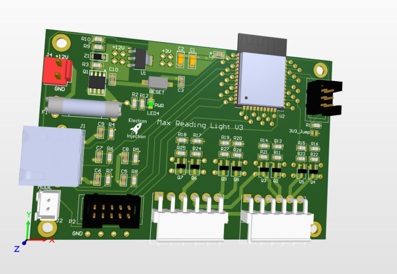
Requirements: This was a basic project. The ESP32 is overkill for this, but I had it on hand. For linear faders that are normally used on a mixing console create voltage dividers that are read by the ADC on the ESP32. The light is dimmed with standard PWM and MOSFETs. Fun artifact. My son wanted … Read more
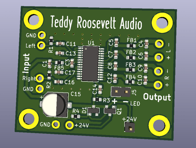
I needed a low power audio amplifier for my home audio setup. Nothing crazy. I basically wanted to match what a car stereo head unit could do. I didn’t want to fiddle with large power and I wanted something cheap. I had done plenty of PCBs for manipulating audio signals, but I had never tried … Read more