Posted on Leave a comment

Add 32 Buttons With Just 2 Pins With MCP23017 Expander

I need about 40 buttons for my synth project.  I’m trying to run the entire synth with a single STM32 Blue Pill.  I’ve already shown how I can run 256 LEDs with 3 pins LINK IT HERE.  Since the MCP23017 is I2C, I could possibly run 128 buttons on 2 pins.  For now, I’m just running two of my Tactile Switch Female Dog boards (each with 16 buttons and a MCP23017 chip).

Stuff I Didn’t Know Yesterday About The MCP23017 Expander

  • I needed to power cycle this chip quite a bit when it didn’t act as expected.  If you start to lose your mind, go ahead and lose it.  Then kill the power for a second.
  • When using the internal pullups, we are in active low land.  Pushing the button gives a zero.  That’s normal.  I got confused when using the onboard STM32 Blue Pill LED as the stupid thing is also active low.  Apparently, I can handle only one active low thing per week.

I debated whether I wanted to use a library or just bang it out with Wire commands.  It’s really all the same, but I guess the library saves 2 seconds of work (at what cost?).  I opted for the Adafruit MCP23017 library, but I’m keeping a link close by for the tutorial using Wire so I don’t have to think or open a datasheet today.

Code For A Single MCP23017 Expander

#include <Arduino.h>
#include <Wire.h>
#include <Adafruit_MCP23017.h>
 
#define ONBOARD_LED PC13
 
// Connect pin #12 of the expander to PB6  I2C clock
// Connect pin #13 of the expander to PB7  I2C data
 
Adafruit_MCP23017 mcp;
 
void setup()
{
    // The address is specified using the A0, A1, and A2 pins
    mcp.begin(); // use default address 0, otherwise, the address needs to be defined
 
    for (int i = 0; i < 16; i++)
    {
        mcp.pinMode(i, INPUT); // MCP23017 pins are set for inputs
        mcp.pullUp(i, HIGH);   // turn on a 100K pullup internally
        delay(10);
    }
    pinMode(ONBOARD_LED, OUTPUT); // use the c13 LED as debugging
 
    // Sanity check to confirm functionality with onboard LED
    for (int i = 0; i < 8; i++)
    {
        digitalWrite(ONBOARD_LED, HIGH);
        delay(100);
        digitalWrite(ONBOARD_LED, LOW);
        delay(100);
    }
}
 
void loop()
{
 
    // Check for a button press of any button.  A LOW indicates a button press
    if (mcp.digitalRead(0) == 0 ||
        mcp.digitalRead(1) == 0 ||
        mcp.digitalRead(2) == 0 ||
        mcp.digitalRead(3) == 0 ||
        mcp.digitalRead(4) == 0 ||
        mcp.digitalRead(5) == 0 ||
        mcp.digitalRead(6) == 0 ||
        mcp.digitalRead(7) == 0 ||
        mcp.digitalRead(8) == 0 ||
        mcp.digitalRead(9) == 0 ||
        mcp.digitalRead(10) == 0 ||
        mcp.digitalRead(11) == 0 ||
        mcp.digitalRead(12) == 0 ||
        mcp.digitalRead(13) == 0 ||
        mcp.digitalRead(14) == 0 ||
        mcp.digitalRead(15) == 0)
    {
        digitalWrite(ONBOARD_LED, LOW); // Turn on the dumb, active low PC13 onboard LED
        delay(1000);                    // Keep the LED on a second.
    }
    else
    {
        digitalWrite(ONBOARD_LED, HIGH); // Turn off the dumb, active low PC13 onboard LED
    }
}

Code For 2 Simultaneous MCP23017 Expanders (32 Buttons)

#include <Arduino.h>
#include <Wire.h>
#include <Adafruit_MCP23017.h> 

#define ONBOARD_LED PC13

/********** HARDWARE *****************/
// Connect pin #12 of the expander to PB6  I2C clock
// Connect pin #13 of the expander to PB7  I2C data
// Remember that I2C requires pullups on clock and data pins.
// I used 2.2k resistors because I mindlessly read it on the internet
// From a guy who typed wth confidence

/********** NOTES ********************/
// If the board acts stupid and you don't want to blame yourself,
// power cycle your microcontroller and the MCP23017

Adafruit_MCP23017 mcp1; // Create an object for the first board.
Adafruit_MCP23017 mcp2; // Create an object for the second board.

void setup()
{
    // The address is specified using the A0, A1, and A2 pins
    mcp1.begin();    // use default address 0, otherwise, the address needs to be defined
    mcp2.begin(001); // make sure to give A0 5V.

    for (int i = 0; i < 16; i++)
    {
        mcp1.pinMode(i, INPUT); // MCP23017 #1 pins are set for inputs
        mcp1.pullUp(i, HIGH);   // turn on a 100K pullup internally
        mcp2.pinMode(i, INPUT); // MCP23017 #2 pins are set for inputs
        mcp2.pullUp(i, HIGH);   // turn on a 100K pullup internally
    }
    pinMode(ONBOARD_LED, OUTPUT); // use the c13 LED as debugging

    // Sanity check to confirm functionality with onboard LED
    for (int i = 0; i < 8; i++)
    {
        digitalWrite(ONBOARD_LED, HIGH);
        delay(75);
        digitalWrite(ONBOARD_LED, LOW);
        delay(75);
    }
}

void loop()
{

    // Check for a button press of any button.  A LOW indicates a button press
    // There is surely a smarter way to do this, but that never stopped me.
    if (mcp1.digitalRead(0) == 0 ||
        mcp1.digitalRead(1) == 0 ||
        mcp1.digitalRead(2) == 0 ||
        mcp1.digitalRead(3) == 0 ||
        mcp1.digitalRead(4) == 0 ||
        mcp1.digitalRead(5) == 0 ||
        mcp1.digitalRead(6) == 0 ||
        mcp1.digitalRead(7) == 0 ||
        mcp1.digitalRead(8) == 0 ||
        mcp1.digitalRead(9) == 0 ||
        mcp1.digitalRead(10) == 0 ||
        mcp1.digitalRead(11) == 0 ||
        mcp1.digitalRead(12) == 0 ||
        mcp1.digitalRead(13) == 0 ||
        mcp1.digitalRead(14) == 0 ||
        mcp1.digitalRead(15) == 0 ||
        mcp2.digitalRead(0) == 0 ||
        mcp2.digitalRead(1) == 0 ||
        mcp2.digitalRead(2) == 0 ||
        mcp2.digitalRead(3) == 0 ||
        mcp2.digitalRead(4) == 0 ||
        mcp2.digitalRead(5) == 0 ||
        mcp2.digitalRead(6) == 0 ||
        mcp2.digitalRead(7) == 0 ||
        mcp2.digitalRead(8) == 0 ||
        mcp2.digitalRead(9) == 0 ||
        mcp2.digitalRead(10) == 0 ||
        mcp2.digitalRead(11) == 0 ||
        mcp2.digitalRead(12) == 0 ||
        mcp2.digitalRead(13) == 0 ||
        mcp2.digitalRead(14) == 0 ||
        mcp2.digitalRead(15) == 0

    )
    {
        digitalWrite(ONBOARD_LED, LOW); // Turn on the dumb, active low PC13 onboard LED
        delay(1000);                    // Keep the LED on a second.
    }
    else
    {
        digitalWrite(ONBOARD_LED, HIGH); // Turn off the dumb, active low PC13 onboard LED
    }
}
Posted on Leave a comment

140 Resistor Labels for 3D Printed Organizer

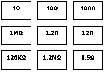
I created paper labels for the E24 Series Resistor Storage Solution on Thingiverse. I liked this approach, but I figured that paper labels would suffice. I used Python to generate the html to avoid any repetitive work.

The already-generated text labels can be found here. Printing in standard “Letter” size in Chrome onto card stock worked for me. The intention is to remove the black box surrounding the resistor values with scissors. (I need a laser cutter!)

The Python file is available here in case there’s anything you may want to customize.

Posted on Leave a comment

New Gear Solved Underextrusion Problems In 3D Printing

Getting a good, strong 3D print is a mess. Maybe another way of saying it is 3D printing with a CR-10 is a labor of love. I’m told the CR-10 is a capable machine. On good days it does what I need. I’m told something like the Prusa i3 requires substantially less tinkering, but then I find the occasional Youtube video where a person has a mess with those, too. It seems there is no 100% perfect solution.

Either way, I’m a tinkerer so here we go.

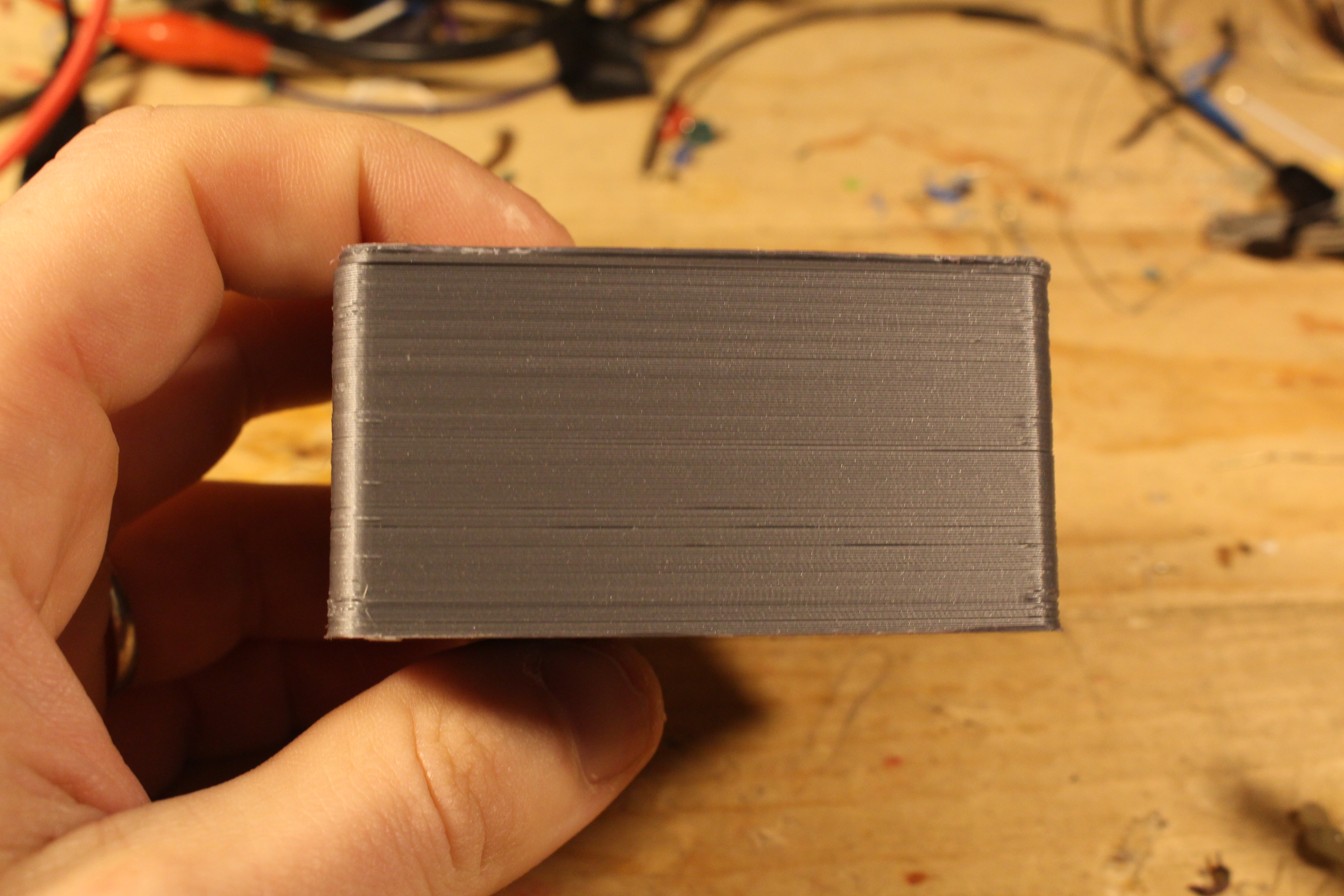
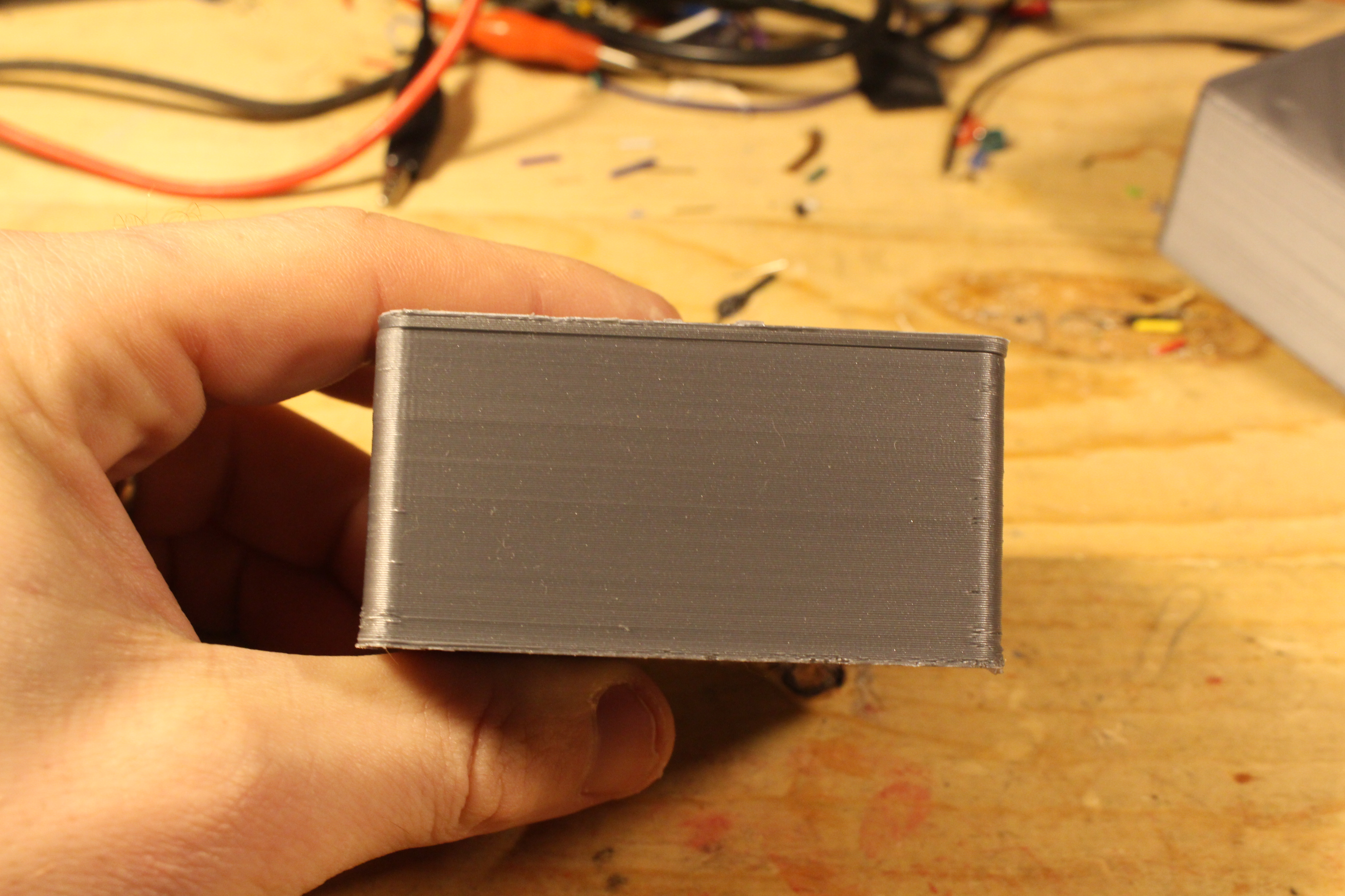
I was facing underextrusion on pretty much every print. The underextrusion wasn’t BAD and my picture of it isn’t great, either, but you could see missing lines from the print that should clearly be in there. Missing layers means the plastic didn’t get squirted where it was supposed to. It makes prints weak. I’m not overly concerned about the aesthetics, but that’s not ideal either.

I picked up a $6 back of steel extrusion gears from Amazon that had much more aggressive teeth than my stock CR-10. My previous gear seemed kinda worthless and it had no shortage of ground-up PLA dust on it. Maybe cleaning that would have helped. I installed the new gear, recalculated my e-steps, and tossed the correct code into Cura. My very first print has zero underextrusion. Problem solved. That NEVER happens.

Note:  Ignore the crunch edges.  That’s the brim that suddenly became a real pain to get off a few weeks ago.  It needs to be sanded off.

Before New Gear


After New Gear

Posted on Leave a comment

PCB Routing Tip

This one is common sense.  I don’t have common sense so I had to learn it the hard way.  When routing tough boards, we have to push the tolerances of our clearances from the trace to the enemy pads.  I’ll define “enemy pads” as those pads we don’t want our current pad to touch.  When doing layout for boards where clearance isn’t an issue, there is no reason to risk wasting your future time.

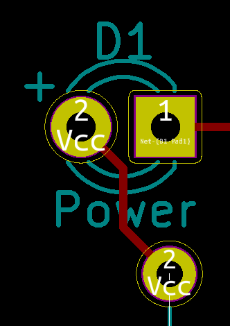
Bad Example

Bad PCB Layout

With our LED here the Vcc flows to the Pin #2 (anode of the LED).  While doing so, it comes quite close to Pin #1.  In this case, there is no reason to route so close to the enemy pad.  The better habit to form would be to start drawing the trace at the anode and avoid Pin #1.

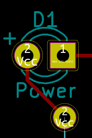
Good Example

GoodLayout

In this good example, I started with Pin #2 of the LED (anode) and came straight down before angling towards Vcc.  The distance between the Pin #2 trace and Pin #1 is maximized without any down sides.

Reality

In reality, this is an incredibly simple example and the LEDs pins give plenty of clearance to solder them later.  So, this example sucks.  However, by developing a habit of maximizing space between enemy traces and pads, we reduce the odds of messy soldering situations.  Last week I received a PCB in SOIC-8 SMD footprints.  I could have taken the approach outlined here with no downside, but instead, I routed my enemy traces way too close to the tiny SOIC-8 pads.  The end result was I ruined one of the pads on the board and wasted 3 hours as I had to solder up a new board.

Posted on Leave a comment

Trump Screws Electronics Enthusiasts

This is not a political thing I’m doing. I have no dog in the hunt over gay rights or the upcoming Russian invasion. I’m just a bad maker and worse engineer. However, I just heard today on the Macrofab Podcast that my unpopulated PCB orders will face a new government tax of 25%. A kit I wanted to sell for $8 will now have to sell for $10. I will sell less. Broke people who want to buy my kits will get less money for their buck.

I don’t know ANY of the details of the current macro trade stuff. I try to stay exactly five years behind on politics. (It’s much more fun.) What I do know is I’m taking a direct hit and my business will directly suffer. It’s one thing to charge more money on the consumer level. It’s another thing to affect the livelihood of small business owners.

Random Application of Tariffs

Another truly intriguing part about these tariffs is how selective they are in their taxation.

Unpopulated PCBs
If a printed circuit board (PCB) is populated with components in China, there is no additional tariff. The reasons for this seem intuitive. Apple has lobbyists. Apple doesn’t want their phones to go up 25%. It’s too bad smaller business owners don’t have any representation.

Flyback diodes
If a diode is to be used for voltage suppression, it is taxed. How in the hell do they know if I’m going to use a diode for rectification or voltage suppression? That’s a good one. Where did they find the tax attorney who has a background in electronics? That’s impressive, actually.

Potentiometers (not resistors)
Fixed resistors don’t get an additional hike. Variable potentiometers go up 25%. Who comes up with this stuff?

Transformers under 1kA
Transformers under 1KA – essentially all consumer grade transformers – go up 25%. The big, industrial transformers face no hit.

I’ve always been perplexed why the tax code favors horse farmers differently than corn or cow farmers. (Each group has varying lobbyist strength.) I’m not aware of the flyback diode industry having a powerhouse lobby that the rectifier diode industry just can’t keep up with.

Where Is The Money Going?

The real question is where is this money going? I did the unthinkable and Googled this tariff mess. I see both China and the US are cranking up their taxes. Ok. Is this to pay off the debt? Are they building a new Hoover dam? Are we invading a new country? I’m just trying to figure out why we’d reduce US prosperity and increase the prices of U.S. manufactured goods. If I know where my money (and business) are going, I’ll be more inclined to pony up.