Posted on Leave a comment

Backlit Panel Engraving Using CNC – Experiment 001

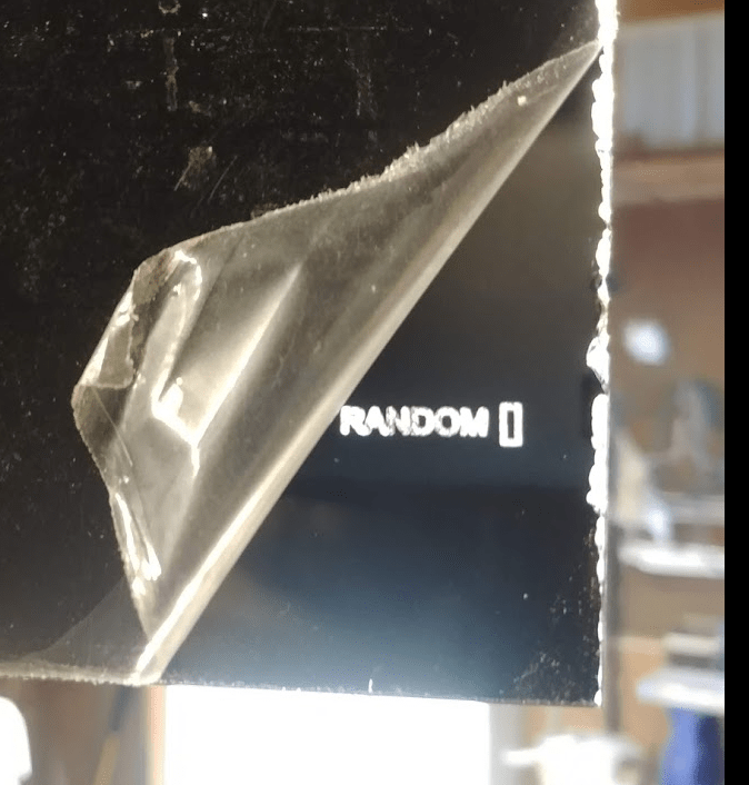
I did some work with the CNC for engraving onto acrylic which I painted black on one side and engraved backward. The idea is the black will ultimately be the back of the front panel. Because the acrylic is very transparent, the engraving is still 100% visible. Because the acrylic is super flat and shiny, it’s as if we put several mm of clear coat or epoxy on top. This epoxy-like effect tends to improve a fairly crude process which is little more than scratching and scraping.

While I should probably start with something easy (NEVER!!!), I decided to jump right into milling extremely small text.  The right call would have been to have engraved a 6″ tall letter A or something equally worthless to me.  Instead, this text 2.159mm tall in Fusion 360.

First off, my conditions.

1) I’m using a bargain-basement 400w spindle-equipped CNC. Engraving puts almost no demands on the rigidity of the machine.

2) I did make a wasteboard using MDF by Facing the top with my CNC. This was a great exercise because it turned out that the machine was highly unoptimized previously and the cut was nowhere near flat. This prompted me to tweak the machine and what I ended up with is light years flatter. I think it’s important to mention this step as the engraving I’m up here is dealing with incredibly low tolerances. If one side is 0.2mm too low or too high, the results will be unusable.

3) I’m using a “nicer” Jerray bit from Amazon with a 0.25mm tip.

The Long Term Goal

This is a bit abbreviated.  The rectangles to the left of the words are buttons.  The rectangles to the right of the words are LEDs.


Today’s Goal

I don’t particularly love the font I have, but I want to see a real-life version before making any major decision changes.  This is a first-draft type of thing to develop a base of knowledge.  A final product could use any number of technologies to get something closer to what Apple or Samsung may crank out.  For now, I’m just getting my toes wet.  Most importantly, I need to see if the font spacing is acceptable.  It’s impossible to gain any context at all as to what the spacings mean in real-life terms from the computer screen.  Again, this text is 2.1mm tall.  (I measured the small text on the TI-36x calculator and ran with that.)  For now, I need to layout a PCB that will hold 16 buttons and 84 LEDs.  I can’t do that until that rectangle around the text is at a realistic size.


The Process

Take acrylic and put 3 or 4 layers of flat black paint.  I don’t know if it has to be flat.  I used flat black.  Let is dry for 3 months.  I’m not sure how long it has to dry.  I did 3 months.  3 days would probably work just fine.   I set up Fusion 360 to mill backward.  That basically meant a lot of goofing around to be sure that the top of my model was actually the part that was painted black.   It was a little screwy to pull off but I’m still far from an expert in Fusion 360.

Feeds and speeds aren’t a huge deal to engraving (at least compared to milling aluminum or something), but here they are.

Multiple Depths 0.13mm

Maximum Depth 0.65  (it should be 5 passes)

I swipped the idea of the maximum depth of 0.65mm from a Youtube video:  https://www.youtube.com/watch?v=Va0h5YpRqKE

Here’s the cliff notes.
30-degree engraving bit
maximum depth 0.5mm
220mm / min feed rate
He used a cleanup pass which appears to be an identical, redundant pass
Then a 3rd pass. Max depth 0.65mm.
Then a 4th pass.


My Results

First off, I never got anywhere near 4 or 5 passes.  After 1 pass I was too deep.  I did a test in wood and thought I went too deep on the first pass.  So, I set the Z axis to be 0.2mm too high on the first pass.  As expected, the bit did not make contact with the acrylic on that first pass.  On the second pass, you can see “ANDOM”.   The machine was beginning the 3rd pass on the “R” when I hit stop.  I could tell that R was way too deep and therefore thick.


Areas of Improvement

Again, this is 2.1mm height text.  If I were engraving the Playboy bunny logo at 18″ height or something (interesting, that’s the first thing that popped in my head), I’d probably be content.  It’s clear that any CNC process for letters this small is going to require ridiculously sharp engraving bits.  My Jerray engraving bit doesn’t come across as “ridiculously” sharp.  It has a small tip, but it wasn’t intended to scrape a single atom at a time.

  1.  The easy solution is to get some 0.1mm tip bits. They are amazon.  I’m sure they aren’t the highest quality (whatever that means), but they are a good place to start when looking at proof of concept.
  2. I wasn’t thinking and I used my $10 Z-axis Zeroing tool.  For the record, the only reason I bought a zeroing tool was that I wasn’t happy with the tolerances of using scrap aluminum.  It turns out the one I bought doesn’t have the best tolerances either.  After buying it, I wrote down in my notes to only use it when the height isn’t hyper, hyper important.  Oops.  I forgot about that and used it on so a CNC job where height was hyper hyper important.  I should have used a piece of paper to get the zero.

So, it’s hard to say whether the Z-axis height was a major factor.  I’m thinking it wasn’t, actually.  I  applied the top+0.2mm offset from the beginning to ensure the first pass did nothing.  That worked correctly.  However, the next pass SHOULD have been 0.7mm above the height of the acrylic as I only dropped down 0.13mm .  It wasn’t.  It carved.  It’s possible I goofed up something in Fusion 360 and dropped down more than 0.13mm.  That’s highly probable, actually.  So, it’s up to Matlock to find out how far I actually dropped for the first layer that actually cut.  Assuming I set up Fusion correct, we were less than 0.13mm.  That’s not much room for error.


The Long Term

I think the CNC may be fine for getting a rough idea of what I’m after, but it’s going to get the mega pro results I’ll want in the future.  In particular, this was a One Line Font.  That means it’s ideal for small font engraving on the CNC, but it has no detail to it and certainly isn’t fun.  I had Terminator font yesterday that I vastly preferred, but all the factors of the CNC limit the resolution.  If I want to have real fun with the font, I may have to go with an acrylic and laser cutter combination or maybe some kind of silkscreen option.  (Not sure on either of those yet, btw.)

With all that said, there are those hyper nerds (among the highest compliments a person can receive, btw)  that make fighter jet cockpits. I’ve seen panels engraved with CNC that look damn good.  I can’t say if their design parameters were the same as mine.  Further investigation is required.


Conclusion

If I’m going to use a CNC and I somehow get tighter lettering than this, I still need to space out the letters a bit.   Do I have enough space allocated for text between my button and my LED?  I don’t know.  BLA!  It depends.  I could space out this boring font to something that looks even more boring to improve the CNC results or I could go with Terminator font and a laser….maybe.  (I’m guessing.)  I believe the answer is I need a laser cutter yesterday.  More toys!!  Alright!!!!

Experiment 002

I gave it another try.

1) I used a 0.1mm bit. I measured it as a 9 degrees, but I believe it said 10 degrees on the ad. The bit was a cheapo bit from China and had no brand name I recognized.

2) I set a maximum dropdown of 0.05mm.

As you can see the results are good. This pic was before I washed the dust out. I wouldn’t say it’s exactly mass-production quality, but it totally suffices for prototyping. Again, the first pass did nothing. The second pass was all that was needed to get the results you see here.  The top is the new one with the 0.1mm bit.  The bottom one is from Experiment 001.

Full Panel

I decided to try milling the entire panel with 16 parameters. Even though I’m using a wasteboard that I leveled to the CNC, there is substantial height variation. Of course, we are talking about hundredths of millimeters here. Using the same maximum dropdown of 0.005mm, I found that the letters closest to where I zeroed the CNC came out great on the first pass. Some lettering didn’t come out until the 5th pass as you can see here.  If you look in the bottom right, you can see that the engraving wasn’t thick enough to cut through the black spray paint.  However, other parameters were cutting uncomfortably deep.


Here’s what it looks like after washing the dust off.  The Legato parameter received only one pass.  Tremolo, on the other hand, got hit by many.


Posted on Leave a comment

Solved: G28 Causing CNC Crashing From Fusion 360 Generated GCode

For some time I struggled with the default Gcode generated by Fusion 360 on my CNC machine. The G28 command was causing the tool to go straight to the top edge of my project and scrape the living crap out of it. My temporary solution in a pinch was to remove the G28 commands from the Gcode manually. This was a hassle and it turns out that the solution is hyper quick and robo easy.

As far as I can tell, G28 is saved in EEPROM. This means that the G28 setting is still there even after I kill the power to my CNC machine and restart. (My CNC was a kit that came with an Arduino Uno and the cheapo red CNC board).

Solution:

  1. Put the CNC tool thing in a safe position. (Crank the Z-axis pretty much to the top. Put the x and y somewhere close to where you generally put your project.)
  2. Enter: G28.1 in the command line of your software.

That’s it.  This saves a new G28 point.  It’s an absolute position that the CNC should remember.

It turned out that G28 was previously set with a Z value that happened to be atrociously close to where I usually did my grinding and engraving. Fusion 360 has the G28 Z0 setting there as a safety measure. Unfortunately, that only works if G28 is set to a safe point. If it’s set to a dangerous point, the problem is only made worse.

Brandon