Believe it or not this is a fully functional music synthesizer with fully every possible parameter tweakable and can save presets. The synth sound horrible, but that was by design.
The YM3812 chip is from an old Soundblaster card from back in the Reagan days. This thing sounds like bad dog stuff. It’s so bad it’s fun. I fell in love with this little SPI chip. Designing a full blown synthesizer with hardware interface ended up being a fairly atrocious amount of work, but I was graduated and unemployed. The intention was to take what started out as an Arduino project and move into a legit project.
I ran into problems with this one on the mechanical side. I needed a way for buttons to feel “good” and I needed a user interface that felt sturdy….like I could throw it down the stairs and it not break. Of all theory of magnetic fields and high speed signal propagation I have studied, I had no background in making a product tough. So this is a fully functional synthesizer that worked in prototype mode, but by the time of V2 I was bogged down by the mechanical end and working a full time job. Eventually, it was out of sight and out of mind. I would love to go back now and slaughter this one.
Microcontroller: STM32 Blue Pill
I was really into these STM32 Blue Pills in 2020. They provided tons of bang for the buck, got me into Cortex M3 32-bit land, and were a big step up from the Atmega328p microcontrollers in the Arduino clones I had laying around. The price was basically the same. I ended up ditching the Cortex M3 because when it came time to design PCBs without modules, the MPN: STM32F103C8T6 was very expensive and had a lead time of a billion years due to the supply chain nasties that didn’t really go away until 2023 or so.
2020 = Mechanically Awful!
When I got my job at Macrofab as a “circuit board analyzer”, I had not studied many products for how to “do it”. I was coming from 4 years of aggressive Arduino hobbyist work followed by 4 years of hell in school and trying to put it all together. You can see that here. I just used a 3/4″ wooden box with butt joints as my “enclosure”. It’s one way to do it, but it’s a dumb way.

You can see from this rear view how much empty space I was working with. Granted, for this phase of the prototype it didn’t matter. I was experimenting with board-to-board connections using 2.54mm which was definitely the right track.
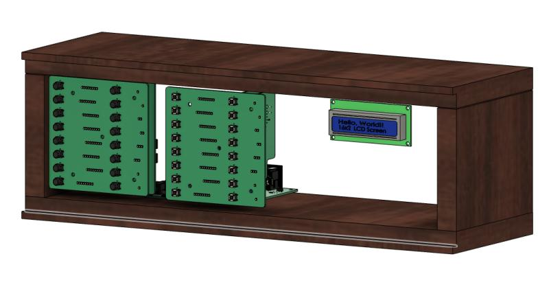
Looking at the front with the pretty cover removed, you could see I had 2 PCBs for the switches. This strikes me as expensive at the moment, but I say that about air, too. These front panel PCBs contained the switches but also contained the LEDs that were used to indicate the level/intensity/setting of every possible parameter on the synths.
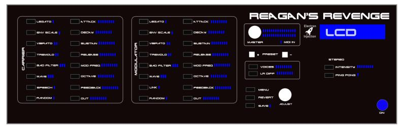
It makes more sense if you look at what I had planned for the front panel. This would have been a 3U rack, if I remember correctly. My gut says this is a $1,000 product when I look at it. I had temptations to do all of this GUI stuff on a $70 tablet and call it a day. Talk to the main microcontroller through UART / bluetooth / wifi / whatever. That approach would have been radically cheaper.
Below is the money shot.
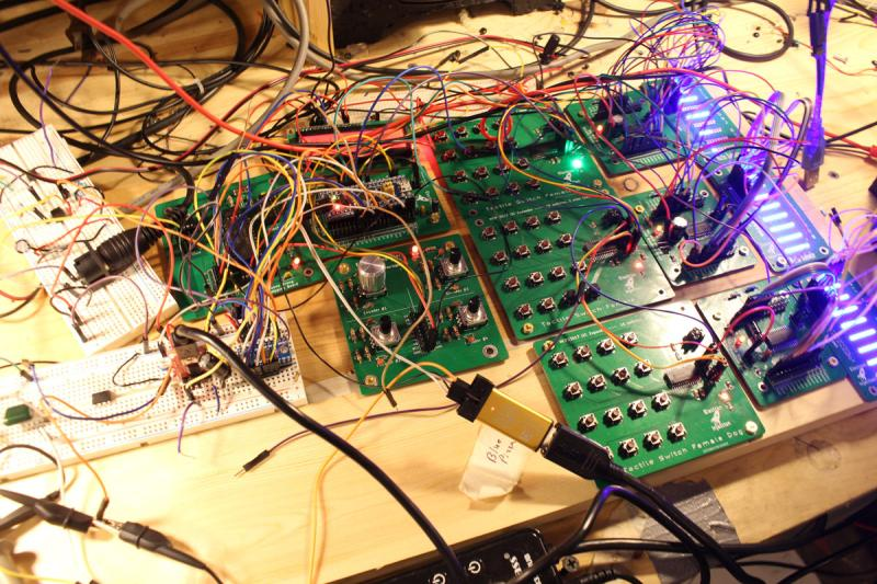
On the far left breadboards you can see old-school MIDI inputs. Just to the right of that is the actual YM3812 audio circuit. I’m trying to remember if I had 2 of these. I believe I did so that I could have more voices. You could argue the point using a primitive junk 80’s chip is to be limited, but my brain doesn’t work that way. I wanted the brain to be awesome. With more voices, I could detune one chip slightly and that allows for all kinds of big, nasty sounds one may hear in supersaw dance land.
Below the 2 YM2812 synth boards is an encoder PCB. It has 4 encoders but I was only using one or two of them. I had built that as a development tool back in the day and got plenty of use out of it on the breadboard.
To the right you can see the PCBs with 16 switches each. These, too, were prototype tools I developed. I need to look up the chip. I used a SPI expander so that I could have a ton of buttons with only only the CS, MOSI, MISO traces.
To the left of that was the TM1640 LED drivers. I need to look up how I drove these LEDs. Now I don’t remember and I’d like to pick my brain. I may have put real thought into this and came up with an interesting solution. I bet I came up with a matrix array thing. I’m not sure how I’d have enough IO otherwise.
On the far right, you can see the blue LEDs that were used to indicate level.